Cross-shaped ultrasonic array sensor and method for transformer partial discharge localization

An array sensor, ultrasonic array technology, applied in fault location, testing dielectric strength and other directions, can solve the problems of large cross-sectional area, difficult layout and high cost of array sensors

Active Publication Date: 2011-12-14
XI AN JIAOTONG UNIV
View PDF4 Cites 28 Cited by
  • Summary
  • Abstract
  • Description
  • Claims
  • Application Information

AI Technical Summary

Problems solved by technology

In addition, the ultrasonic array with a rectangular surface also brings difficulties to the arrangement between it and the UHF (array).
These all lead to a large cross-sectional area of ​​the (composite) array sensor, and subsequent hardware circuits are bulky and costly

Method used


Image

  • Cross-shaped ultrasonic array sensor and method for transformer partial discharge localization
  • Cross-shaped ultrasonic array sensor and method for transformer partial discharge localization
  • Cross-shaped ultrasonic array sensor and method for transformer partial discharge localization

Examples


Embodiment Construction

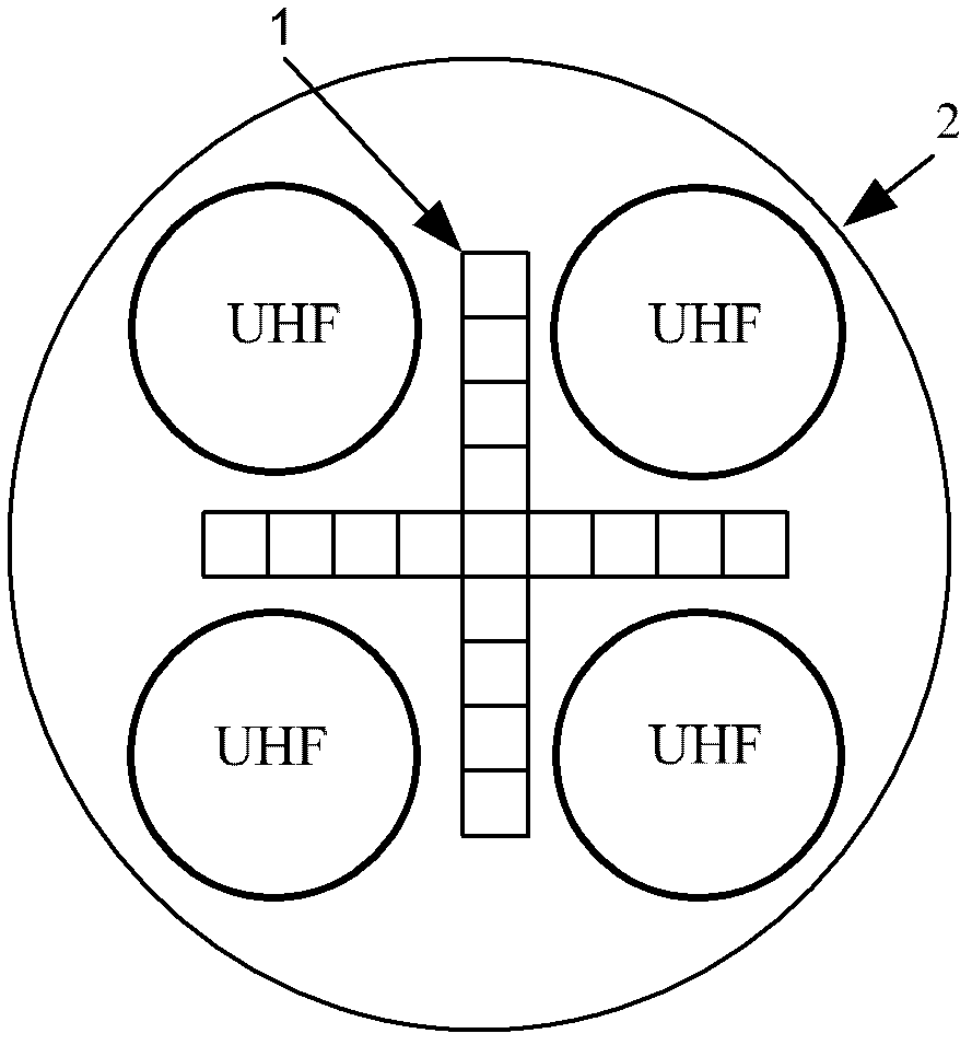
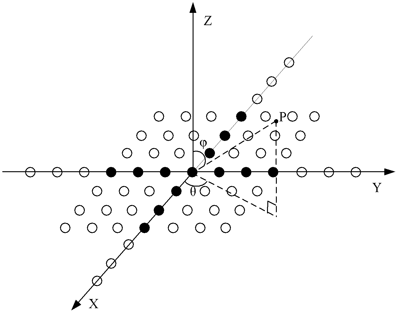
[0017] Virtually expand the original cross-shaped array by using high-order cumulant processing technology, and establish a mathematical model of the cross-shaped ultrasonic array. The array elements are located on the X and Y axes and arranged at equal intervals. Point P is the partial discharge position, and θ and Represent the pitch angle and azimuth angle of the incoming wave direction, respectively. The coordinates of the virtual array elements can be obtained by subtracting the coordinates of each array element from each other. The positions before and after expansion are as follows: figure 2 As shown, the solid circle is the actual array element position, and the hollow circle is the virtual array element position. Depend on figure 2 It can be seen that the expanded array elements are planar arrays.

[0018] The steps of using the extended array to locate the partial discharge are: calculating the fourth-order cumulant matrix Rcum of the ultrasonic signal received ...


PUM


Abstract

The invention discloses a cruciform ultrasound array sensor and method for positioning transformer partial discharge. The ultrasound array sensors are arranged in a cross way and at equal intervals; the number of piezoelectric sensors is 5 to 300; ultra-high frequency sensors are located around the cruciform ultrasound array sensor; the outside of the sensor is a metal shield and the bottom surface of the sensor is a matching layer. The method comprises the following steps of: virtual expanding the cruciform array by high-order cumulant technology; estimating direction of the expanded virtualarray by a spatial spectrum estimation algorithm; and then synthesizing ultrasound beam of at the estimated direction, combined with electric pulse or ultra-high frequency electromagnetic signal produced by partial discharge, obtaining propagation delay of the ultrasonic wave in the transformer and further positioning the transformer partial discharge. The subsequent hardware circuits of the sensor can be greatly decreased, the production cost can be saved; moreover, Gaussian colour noise can be effectively inhibited, and the practicability of array technology in the partial discharge detection field can be achieved conveniently.

Description

technical field [0001] The invention belongs to the field of high-voltage equipment and test technology, in particular to the detection and positioning technology of partial discharge inside a power transformer. Background technique [0002] Partial discharge will produce electromagnetic waves, sound, light, heat and other physical and chemical phenomena. According to the analysis and processing of these quantities, the location of the partial discharge source can be obtained. The application of array technology to locate partial discharge is a new method that has emerged in recent years. This method has high positioning accuracy and can locate multiple partial discharge sources that occur simultaneously. [0003] However, the current research is generally based on array sensors with rectangular surfaces. To ensure that the array has a sharp enough directionality, the number of array elements needs to be large. In particular, the use of ultra-high frequency signals of parti...

Claims


Application Information

Patent Timeline
Patent Type & Authority Applications(China)
IPC IPC(8): G01R31/12G01R31/08
Inventor 罗勇芬纪海英李彦明
Owner XI AN JIAOTONG UNIV
Why Eureka
Try Eureka