Linear pendant luminaire

a technology of pendant lights and luminaires, applied in fixed installations, lighting and heating apparatus, lighting support devices, etc., can solve problems such as the ceiling getting darker, and achieve the effects of improving the luminaire, brightening the overall area, and effectively providing light to the work surfa

Inactive Publication Date: 2015-10-22
NEXT LIGHTING CORP
View PDF3 Cites 17 Cited by
  • Summary
  • Abstract
  • Description
  • Claims
  • Application Information

AI Technical Summary

Benefits of technology

[0004]A need exists for improved luminaires that effectively provide light to a work

Problems solved by technology

Moving the light closer to the work surf

Method used


Image

  • Linear pendant luminaire
  • Linear pendant luminaire
  • Linear pendant luminaire

Examples


Embodiment Construction

[0023]The invention provides systems and methods for providing illumination. A linear pendant luminaire may provide light to an area. Various aspects of the invention described herein may be applied to any of the particular applications set forth below or for any other types of lighting configurations. The invention may be applied as a standalone device or method, or as part of an integrated lighting system. It shall be understood that different aspects of the invention can be appreciated individually, collectively, or in combination with each other.

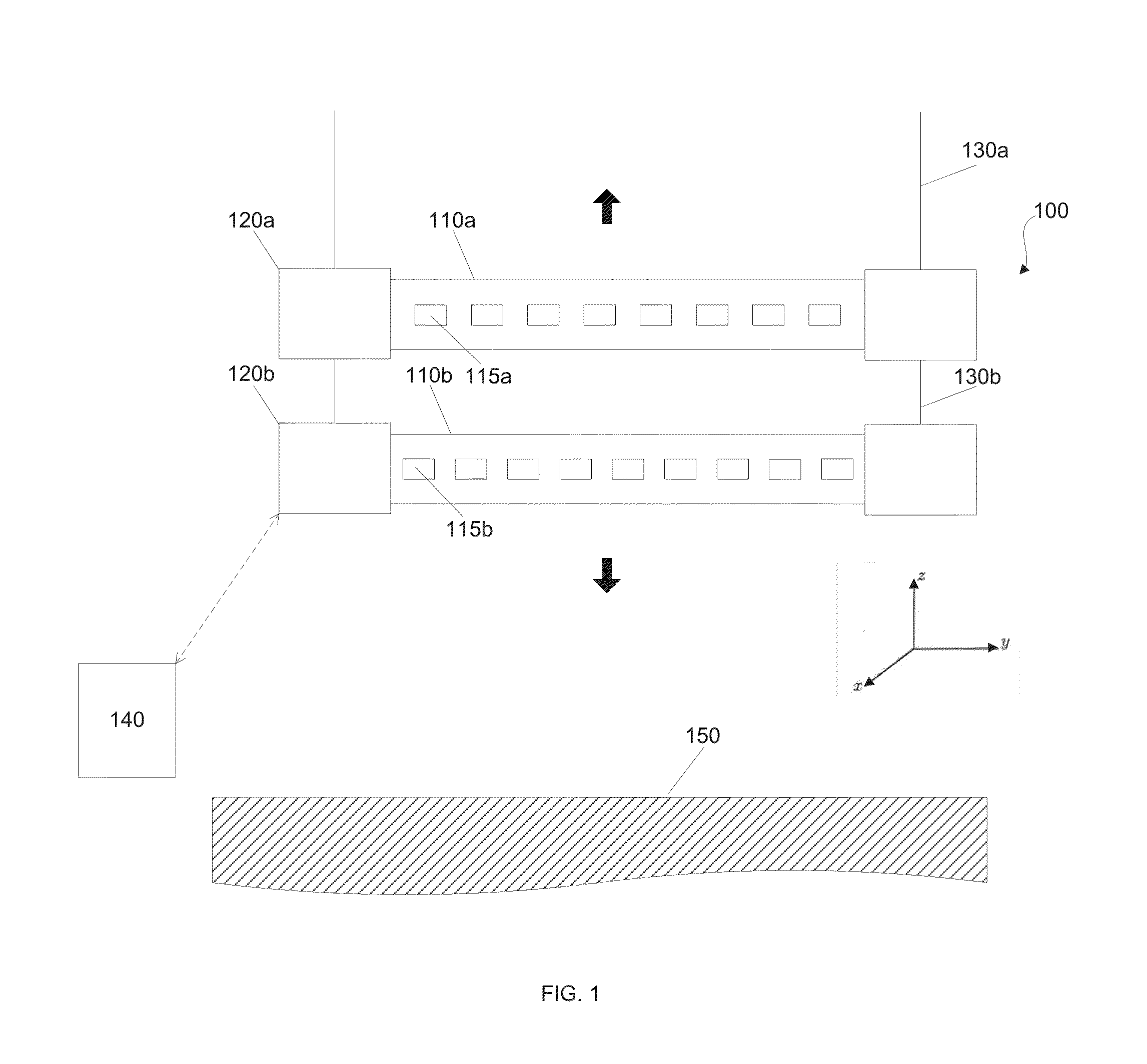
[0024]FIG. 1 shows a high level schematic of a lighting system in accordance with an embodiment of the invention.

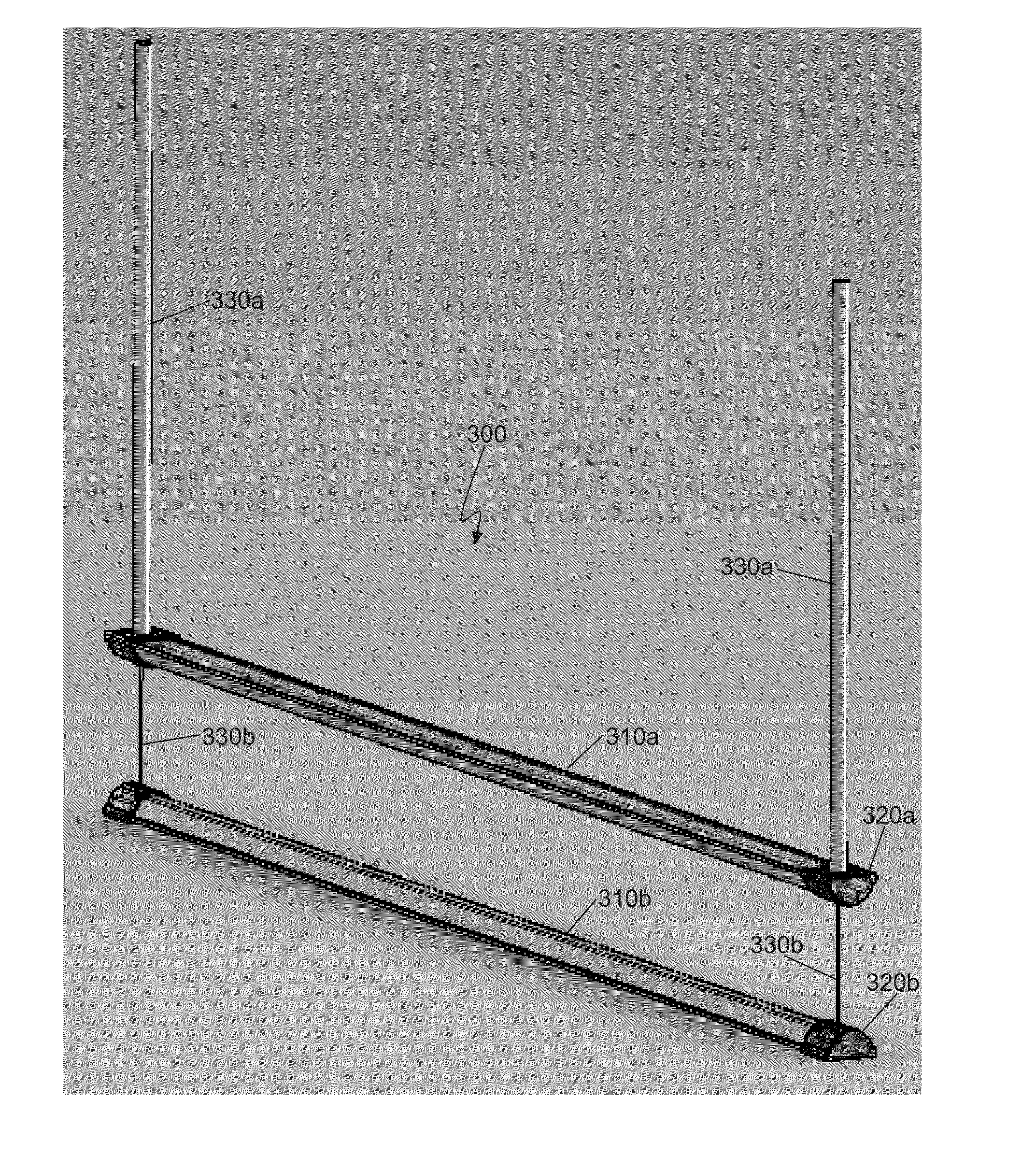
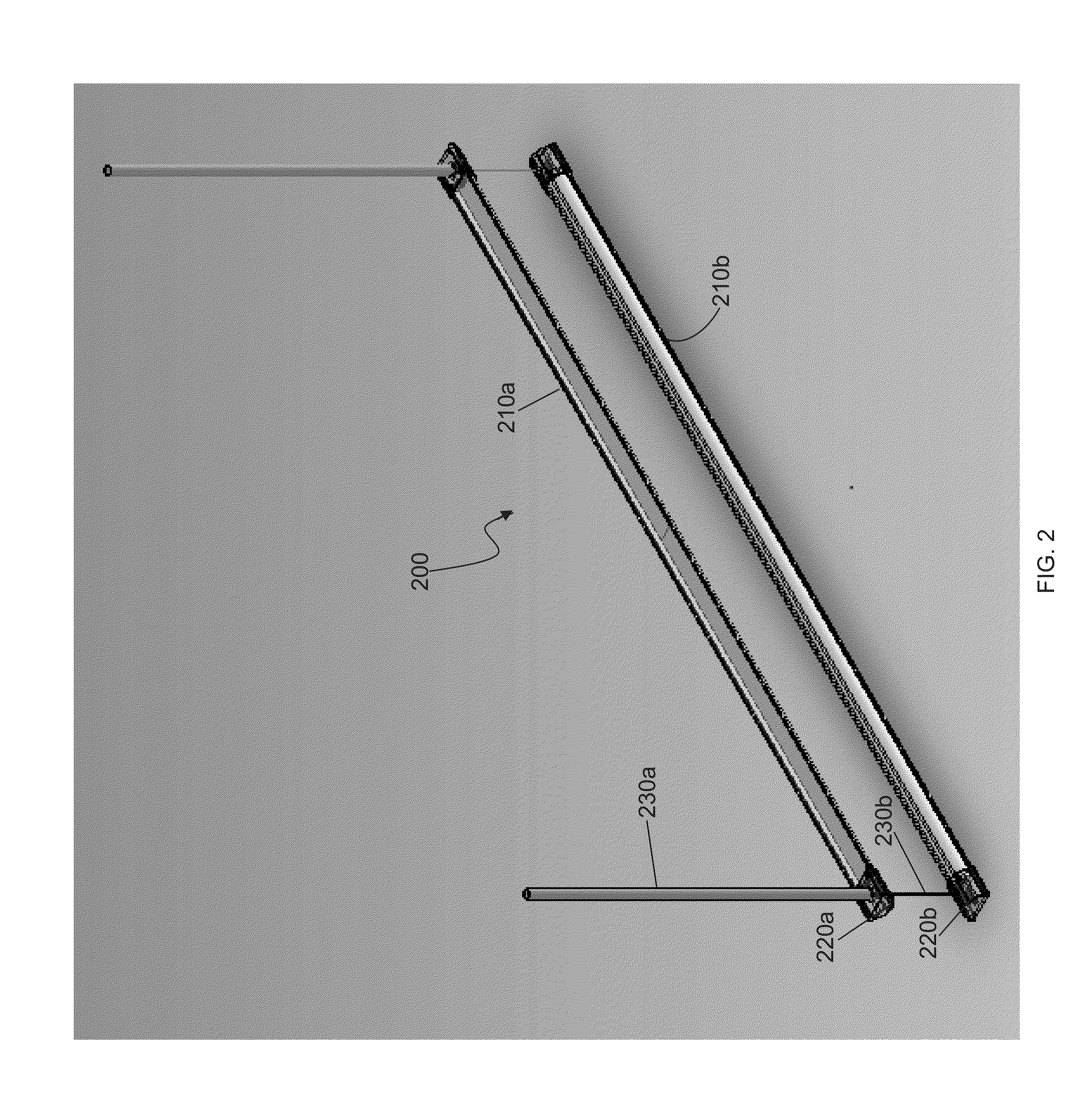
[0025]The system may include a luminaire 100, in accordance with an embodiment of the invention. The luminaire may be configured to function as a fluorescent tube replacement, or may be any type of lighting unit configured to illuminate an area or region. The luminaire may it include a body 110a, 110b and one, two, or more end...


PUM


Abstract

A luminaire may be provided having multiple elongated bodies. The light emitted by the elongated bodies may be controlled independently of one another. The position of the bodies relative to one another or a reference point r be altered independently of one another. The luminaire may be a pendant luminaire hat may hang from a surface.

Description

CROSS-REFERENCE[0001]This application claims the benefit of U.S. Provisional Application No. 61 / 940,173, filed Feb. 14, 2014, which application is incorporated herein by reference.BACKGROUND OF THE INVENTION[0002]Large numbers of linear lamps and luminaires are commonly used in commercial buildings and other spaces to provide ambient light in the form of fluorescent troffers. In addition, linear solutions are found in coves and wall washing applications where appearance is important. As the lighting power densities (watts per square foot) continue to drop to reduce energy consumption, there is pressure on the light source to be inherently more efficient and / or be positioned closer to the work surface. Pendant luminaires have been provided to be positioned closer to the work surface.[0003]One consequence of moving the light closer to the work surface is the ceiling gets darker. A dark ceiling can have the generally undesirable impression of being in a cave.SUMMARY OF THE INVENTION[00...

Claims


Application Information

Patent Timeline
IPC IPC(8): F21V23/04F21V23/00F21S8/06
CPCF21V23/0442F21V23/005F21S8/06F21V21/16F21Y2103/10F21Y2115/10F21V29/83F21K9/64F21S8/061F21V23/001F21V23/04F21V23/0435F21V23/0464
Inventor KATONA, THOMAS M.PAOLINI, STEVESOSNICK, RANDALL
Owner NEXT LIGHTING CORP
Why Eureka
Try Eureka