Large Deployable Reflector For A Satellite Antenna

a satellite antenna and deployable technology, applied in the direction of space vehicles, transportation and packaging, aircrafts, etc., can solve the problems of overwhelming failure to achieve satisfactory results in practice, and the construction of the above-described type of reflector is extremely complex

Active Publication Date: 2015-10-22
THALES ALENIA SPACE ITAL SPA
View PDF6 Cites 29 Cited by
  • Summary
  • Abstract
  • Description
  • Claims
  • Application Information

AI Technical Summary

Problems solved by technology

In general, the construction of a reflector of the above-described type is extremely complex, especially when taking into account the strict requirements that the reflector must respect both regarding weight and bulk, which, in the stowed configuration, must remain within certain payload limits of the satellite launcher, and regarding, more in general, the mechanical properties in terms of strength and reliability that the reflector, and the support structure in particular, must have in order to ensure that the movements in the opening phase in orbit are correctly made and that the final deployed configuration of the reflector accurately corresponds to the envisaged design configuration.
Various solutions for large deployable reflectors have been proposed up to now; however, for the above-described reasons, the majority of these have not proved satisfactory in practice.

Method used


Image

  • Large Deployable Reflector For A Satellite Antenna
  • Large Deployable Reflector For A Satellite Antenna
  • Large Deployable Reflector For A Satellite Antenna

Examples


Embodiment Construction

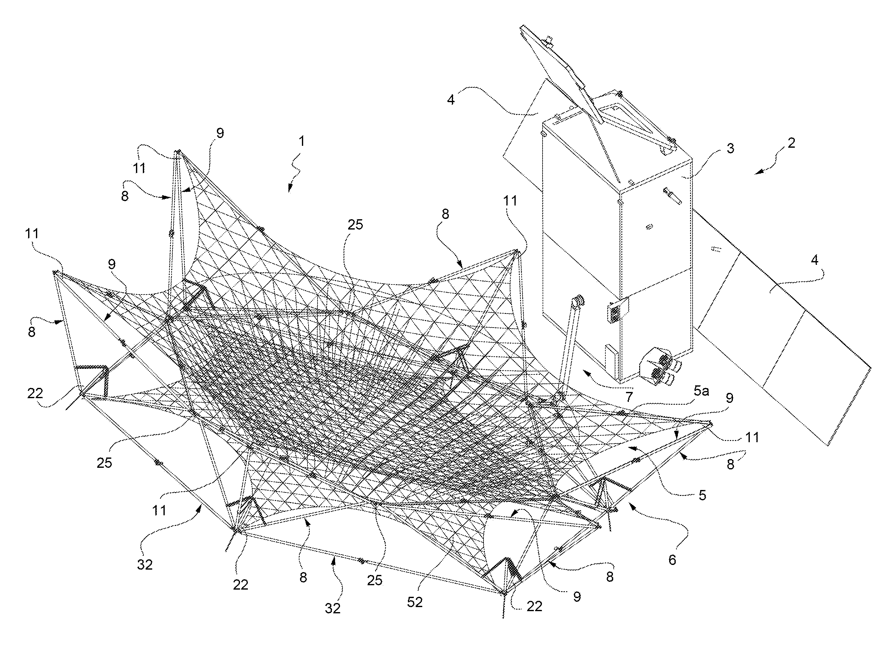
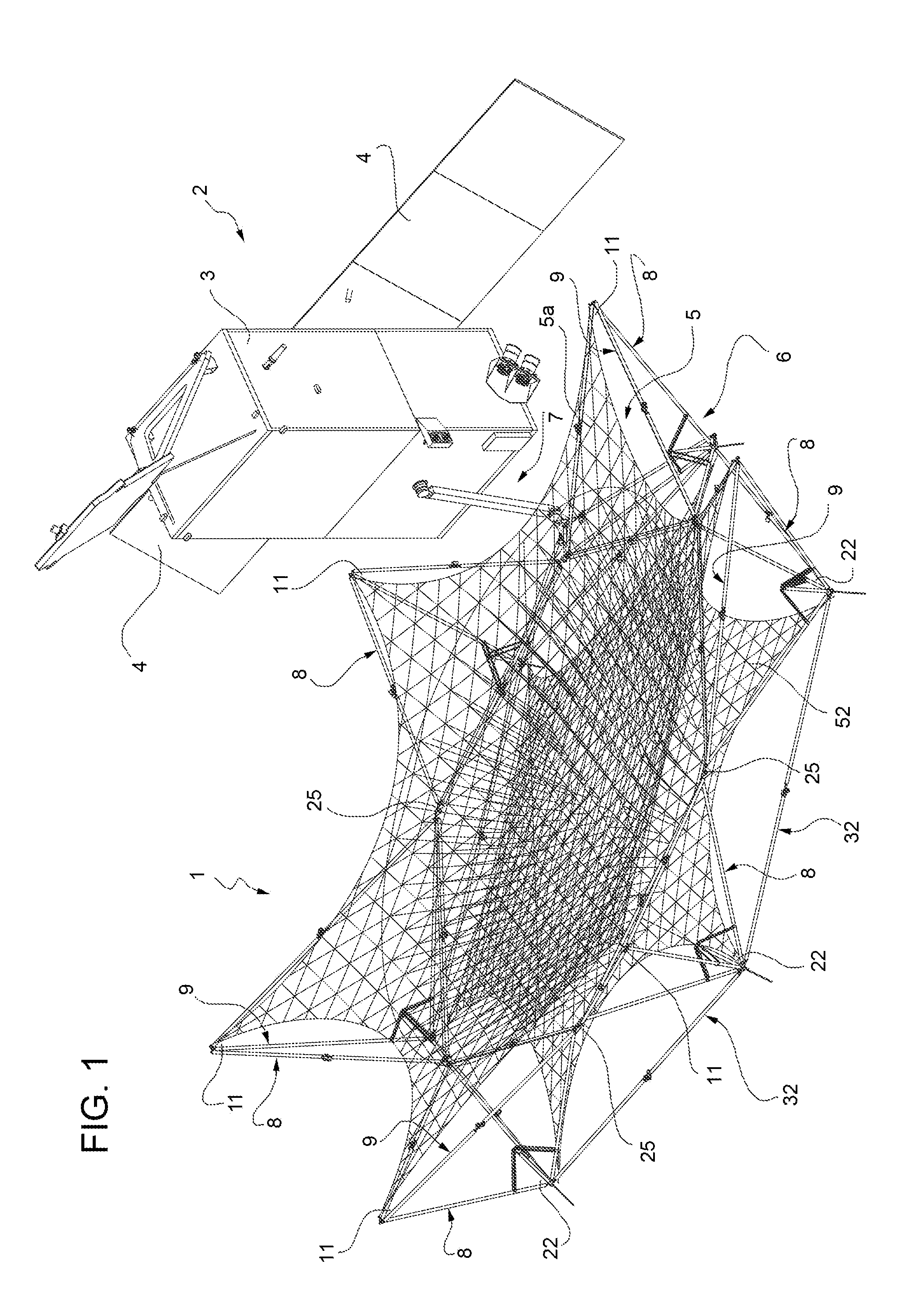
[0034]With reference to FIG. 1, reference numeral 1 indicates, as a whole, a reflector of an antenna installed on a satellite 2 (of known type) for telecommunications, navigation, radio science and / or earth observation. Satellites of this type are normally placed in geostationary orbit and comprise a central module 3, which functions as a transportation vehicle for the antenna and comprises, in a known manner, a plurality of components, including, for example, propulsion and drive devices, thermal control devices, trim and orbit control devices, data processing devices and power supply devices able to transform solar radiation into electrical energy by means of a solar panel system 4.

[0035]The reflector 1 is of the deployable type, or rather is able to assume a compact stowed configuration during the launch phase of the satellite 2 and to autonomously open in space when the satellite 2 has reached a predetermined orbit for assuming a deployed configuration with sufficient rigidity t...


PUM


Abstract

A large deployable reflector for an antenna suitable for being installed on board a satellite and provided with a support structure, a parabolic mirror carried by the support structure and a connection arm for mounting the support structure on the satellite; the support structure being a jointed reticulate structure that is able to assume a compact inoperative stowed configuration and an operative deployed configuration and is composed of ‘n’ elements articulated to form tetrahedrons having respective triangular bases, which are connected to each other at the axial ends of respective first sides and have respective external vertices, which are opposite to said respective first sides and, when the reflector is arranged in the deployed configuration, ideally lie on a cone tangent to the parabolic mirror.

Description

TECHNICAL FIELD[0001]The present invention relates to a large deployable reflector for a satellite antenna.STATE OF THE PRIOR ART[0002]As is known, satellite telecommunications systems use satellites placed in geostationary orbit and equipped with a device capable of receiving, amplifying and transmitting radio signals by means of one or more parabolic antennas.[0003]A relatively recently developed type of satellite antenna is composed of large deployable antennas, namely parabolic antennas having a reflector that is equipped with an articulated support structure able to assume a compact stowed configuration during the launch of the satellite and to automatically open in space when the satellite has reached the established orbital position, for assuming a rigid deployed configuration.[0004]A reflector of this type normally has a diameter of between 5 and 16 metres and has a reflective part that is obviously not rigid, but composed of some kind of light, electrically conductive fabri...

Claims


Application Information

Patent Timeline
Patent Type & Authority Applications(United States)
IPC IPC(8): H01Q15/16
CPCH01Q15/161B64G1/222B64G1/66H01Q1/288H01Q1/28
Inventor MESCHINI, ALBERTORIGATO, RICCARDOSCAROZZA, DAVIDE
Owner THALES ALENIA SPACE ITAL SPA
Why Eureka
Try Eureka