Electrical connector

a technology of electrical connectors and connectors, applied in the direction of coupling device connections, securing/insulating coupling contact members, electrical apparatus, etc., can solve the problems of inconvenient installation, weak assembly strength, time-consuming and laborious, etc., and achieve the effect of promoting the bulk intensity promoting the reliability of the produced electrical connectors

Active Publication Date: 2015-10-22
FREEPORT GUANGDONG PRECISION IND CO LTD
View PDF0 Cites 10 Cited by
  • Summary
  • Abstract
  • Description
  • Claims
  • Application Information

AI Technical Summary

Benefits of technology

[0009]The main purpose of the invention is to provide an electrical connector, in which buckle holes of a lower shell body are riveted to buckling sheets of an upper shell body so as to integrally form the upper and lower shell bodies into one piece, thereby effectively promoting the bulk intensity of the produced electrical connector. Accordingly, the wire can be tightly pressed for avoiding excessive oscillation caused by the rear end of the clamped wire, thereby preventing the internal mechanism of the electrical connector from damage due to the oscillation of the wire and promoting the reliability of the produced electrical connector.
[0012]In the invention, a rear end of the upper shell body is configured with the first buckling sheets, and a rear end of the lower shell body is configured with the first buckle holes. The first buckle holes of the lower shell body is riveted to the buckling sheets of the upper shell body so as to integrally form the upper and lower shell bodies into one piece, thereby effectively promoting the bulk intensity of the produced electrical connector. Two sides of the wire are clamped by the left-rear side plate and the right-rear side plate of the upper shell body, and the wire can be tightly pressed for avoiding excessive oscillation caused by the rear end of the clamped wire, thereby preventing the internal mechanism of the electrical connector from damage due to the oscillation of the wire and promoting the reliability of the produced electrical connector.

Problems solved by technology

In an actual application, because too many components of the front and rear shells exists in a wired position of the wire and the terminal set and geometric structure thereof cannot be perfectly flatten, the rear shell is possibly blocked and not allowed to insertedly engage with the front shell if any protrusion is existed thereon.
Therefore, the internal components of the front and rear shells must be manually pressed and ordered so that a reassembling process can be smoothly performed again, resulting in problems of installation inconvenience, time-consuming and requiring strenuous effort.
When the tail of the forced wire has a large oscillation amplitude, the internal components of the upper and lower shell body of the rear shell are easily loosened, or even the engagement structure is disengaged, deformed, warped or fallen off, resulting in weak assembly strength and short life service.
However, due to a predetermined space to be required for the wired position of the adjacent terminals, it is difficult to realize product miniaturization for the requirement of market diversification.

Method used


Image

  • Electrical connector
  • Electrical connector
  • Electrical connector

Examples


Embodiment Construction

[0026]The following description taking a High-Density Multichip Interconnect (HDMI) electrical connector as an example, is of the best-contemplated mode of carrying out the invention. This description is made for the purpose of illustrating the general principles of the invention and should not be taken in a limiting sense of being applied in the HDMI electrical connector, viz. being applied in other connectors.

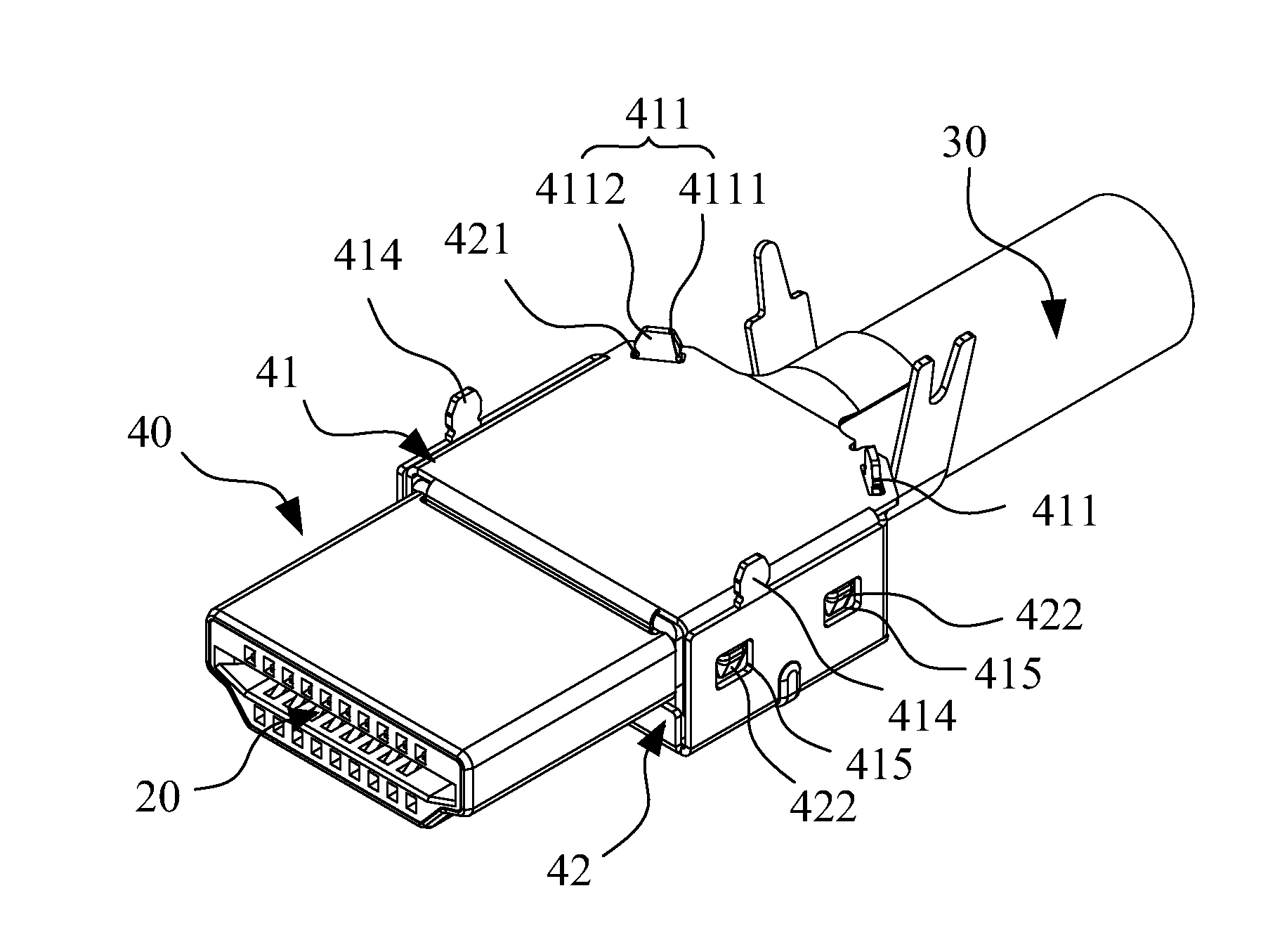
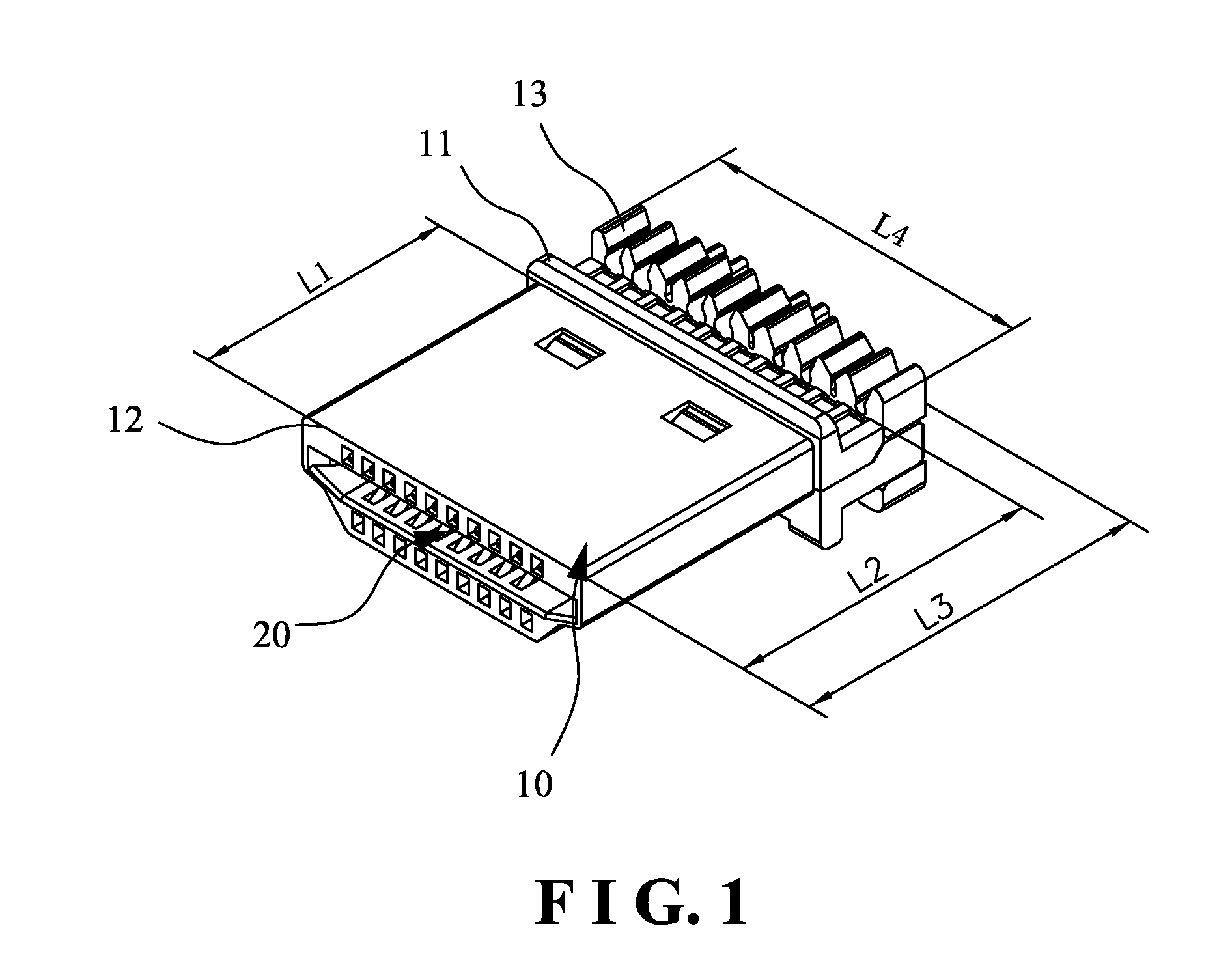
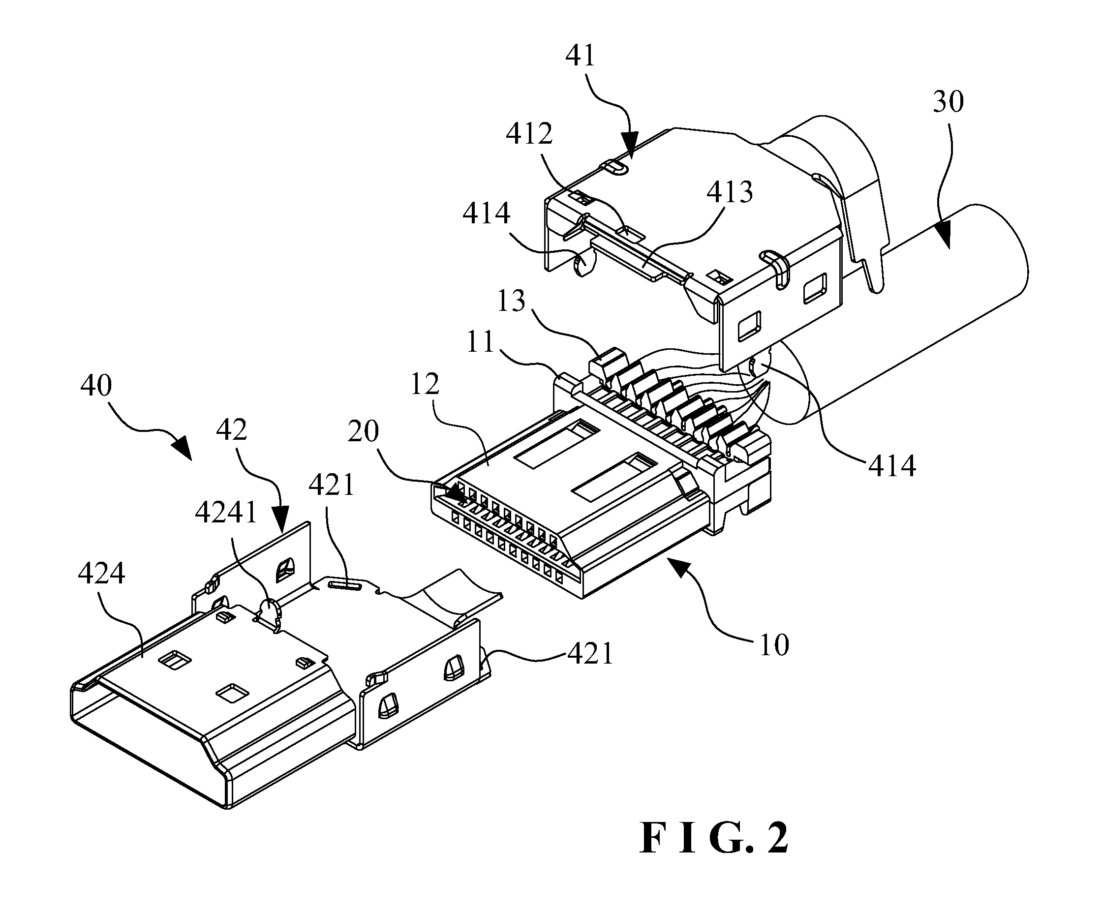
[0027]Referring to FIGS. 1 to 11, a concrete configuration of a preferred embodiment of the invention is illustrated. The electrical connector comprises an insulating body 10, a terminal set 20 insertedly mounted in the insulating body 10, a wire 30 connected to a rear end of the terminal set 20, and a shielding housing 40 wrapped on a wired position of the insulating body 10, the terminal set 20 and the wire 30. Accordingly, a HDMI connection plug can be formed.

[0028]As shown in FIGS. 4, 5 and 6, the shielding housing 40 comprises an upper shell body 41 and a lower shell bod...


PUM


Abstract

An electrical connector includes an insulating body, a terminal set, a wire, and a shielding housing having an upper shell body and a lower shell body. A support part of the first buckling sheet which is penetrated through a first buckle hole of the lower shell body is rivetedly pressed on an outer peripheral edge of the first buckle hole of the lower shell body. An upper side and a lower side of the wire are pressed by a top plate of the upper shell body and the bottom plate of the lower shell body so that the upper and lower shell bodies of the shielding housing can be integrally formed, thereby promoting the bulk intensity of the produced electrical connector, preventing the internal mechanism of the electrical connector from damage due to the oscillation of the wire, and promoting the reliability of the produced electrical connector.

Description

BACKGROUND OF THE INVENTION[0001]1. Field of the Invention[0002]The present invention relates to technical fields of electrical connectors, and in particular relates to a HDMI electrical connector.[0003]2. Description of the Related Art[0004]Conventionally, a High-Density Multichip Interconnect (HDMI) electrical connector includes an insulating body, a terminal set insertedly mounted in the insulating body, a wire connected to a rear end of the terminal set, and a shielding housing sleeved outside the insulating body to form a connection plug.[0005]The shielding housing generally includes a front shell and a rear shell that are commonly designed as two individual parts, in which the front shell is utilized to sleeve outside the insulating body, and the rear shell is utilized to wrap on a wired position of the wire and the terminal set to tightly clamp a rear end of the wire. In the present market, different types of rear shells such as an integrally-formed rear shell and a split-typ...

Claims


Application Information

Patent Timeline
Patent Type & Authority Applications(United States)
IPC IPC(8): H01R13/6581H01R13/40
CPCH01R13/40H01R13/6581H01R13/5808
Inventor TAO, WUSONGWANG, YU
Owner FREEPORT GUANGDONG PRECISION IND CO LTD
Why Eureka
Try Eureka