Chainsaw-type Brush Cutting Assembly

a chainsaw and assembly technology, applied in chainsaws, metal sawing accessories, manufacturing tools, etc., can solve the problems of increasing the amount of effort required by the operator to maintain proper operation, increasing the probability of operator or bystander injury, and generating negative feedback to the operator. , to achieve the effect of reducing vibration, negative operator feedback, and reducing vibration

Inactive Publication Date: 2015-10-29
JOYE DARRELL ANDREW
View PDF22 Cites 2 Cited by
  • Summary
  • Abstract
  • Description
  • Claims
  • Application Information

AI Technical Summary

Benefits of technology

[0003]Through the years, there have been many attempts to develop a compact, lightweight and inexpensive brush cutting assembly to compliment hand-held type gasoline powered vegetation trimmers, which is both safe and effective to operate. U.S. Pat. Nos. 859,554; 1,988,898; 2,992,664; 3,425,467; 4,627,322; 4,989,489; Swedish Patent No. 80,528; and French Patent No. 1,194,641 each disclose circular rotary saw blade assemblies that employ the use of chainsaw chain cutting members or a chainsaw chain affixed to the periphery of the discs but each fails to accomplish the same work capacity with comparable efficiency and safety as the present invention. A significant deficiency of the saw blade assemblies disclosed in the aforementioned patents is their tendency to occasionally generate negative feedback to the operator in the way of “kick back”. U.S. Pat. No. 4,989,489 defines kick back as a cutting assembly's tendency “to give a sudden, forceful and uncontrolled reaction that caused the blade and supporting elements to move suddenly away from the piece being cut”. Kickback increases the amount of effort required by the operator to maintain proper operation and also increases the probability for operator or bystander injury. There are several other deficiencies which the present invention attempt to overcome. Said deficiencies include but are not limited to the amount of time needed to repair, replace or sharpen cutting members as well as a higher cost of operation. It is the assertion of the inventor that these deficiencies exist due to the need to purchase and replace specialized cutting members specific to their respective embodiments as opposed to the present invention, which makes use of a common chainsaw chain.
[0005]While many attempts such as those assemblies in the aforementioned patents exhibit an improvement over flail and string type assemblies for the purpose of cutting and clearing brush, it is the assertion of the inventor that the present invention provides a more practical solution for this long felt need. None of the known prior art discloses a brush cutting assembly which makes use of a common chainsaw chain, propelled around a guide bar by a drive gear member, or “drive sprocket”, whose operation is assisted by two forward and lateral facing stabilizers arms. This assembly is designed to increase productivity while reducing vibration, kickback and other negative operator feedback.

Problems solved by technology

A significant deficiency of the saw blade assemblies disclosed in the aforementioned patents is their tendency to occasionally generate negative feedback to the operator in the way of “kick back”.
Kickback increases the amount of effort required by the operator to maintain proper operation and also increases the probability for operator or bystander injury.
Said deficiencies include but are not limited to the amount of time needed to repair, replace or sharpen cutting members as well as a higher cost of operation.
However the method by which the chainsaw chain is anchored or affixed into the chain track is insufficient and may allow for slipping and binding which results in a significant reduction in productivity.
Also unlike the present invention, the aforementioned embodiment of U.S. Pat. No. 4,627,322 lacks a chain tensioner adjustment which means that once the chainsaw chain becomes worn or stretched, as is normal wear for a chainsaw chain, the cutting blade becomes inefficient, unsafe and ultimately inoperable.
None of the known prior art discloses a brush cutting assembly which makes use of a common chainsaw chain, propelled around a guide bar by a drive gear member, or “drive sprocket”, whose operation is assisted by two forward and lateral facing stabilizers arms.

Method used


Image

  • Chainsaw-type Brush Cutting Assembly
  • Chainsaw-type Brush Cutting Assembly
  • Chainsaw-type Brush Cutting Assembly

Examples


Embodiment Construction

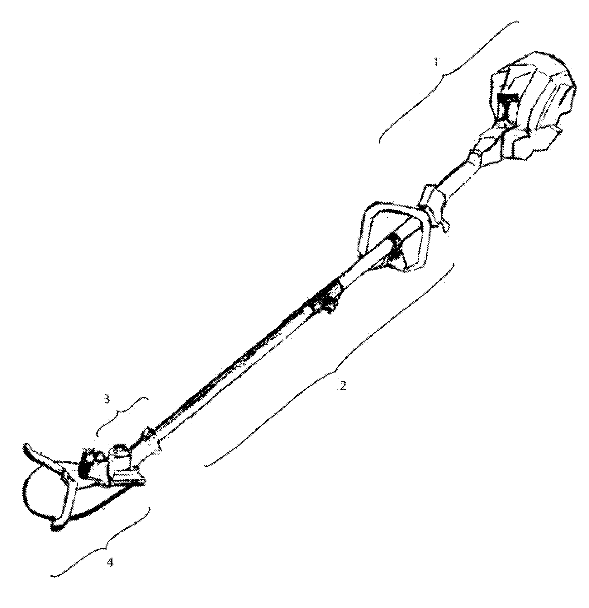
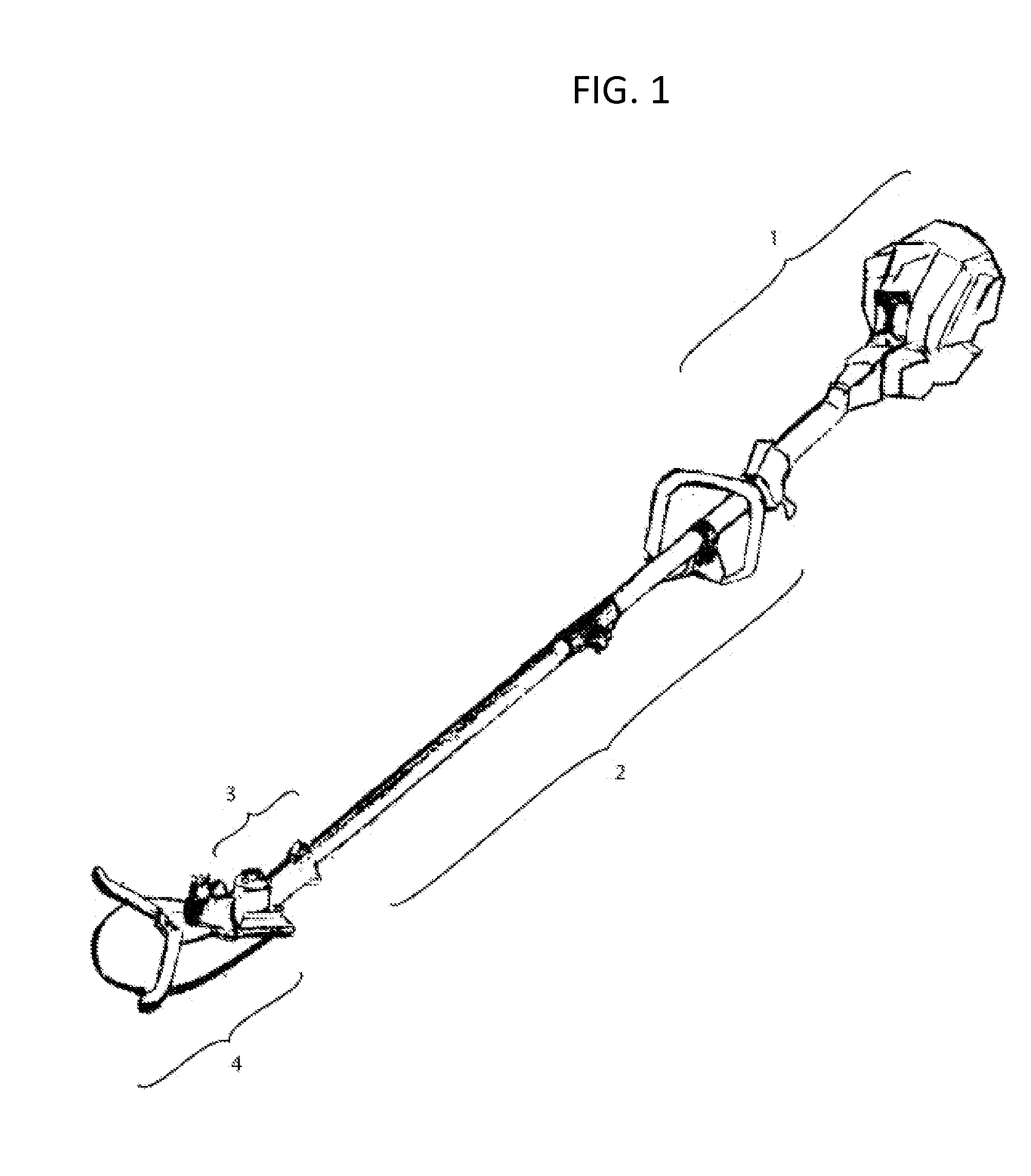
[0010]FIG. 1 shows a conventional brush cutting tool with a power head unit (1) and an elongated internal drive shaft means (2) terminating at the bottom in a gear box housing (3) with an output arbor or shaft (out of view). Said brush cutting tool comprising the preferred power tool with which the present invention is applied, either as a permanently affixed cutting assembly or as an interchangeable cutting implement. In the described embodiment, the invention (4) is permanently secured to the conventional brush cutting tool by way of fasteners which attach the assembly chassis (described below and illustrated in FIG. 2) to the gear box housing. Power is transferred from the conventional brush cutting tool and supplied to the cutting assembly by way of a drive sprocket which is fastened to the threaded end of the output arbor using a conventional nut fastener.

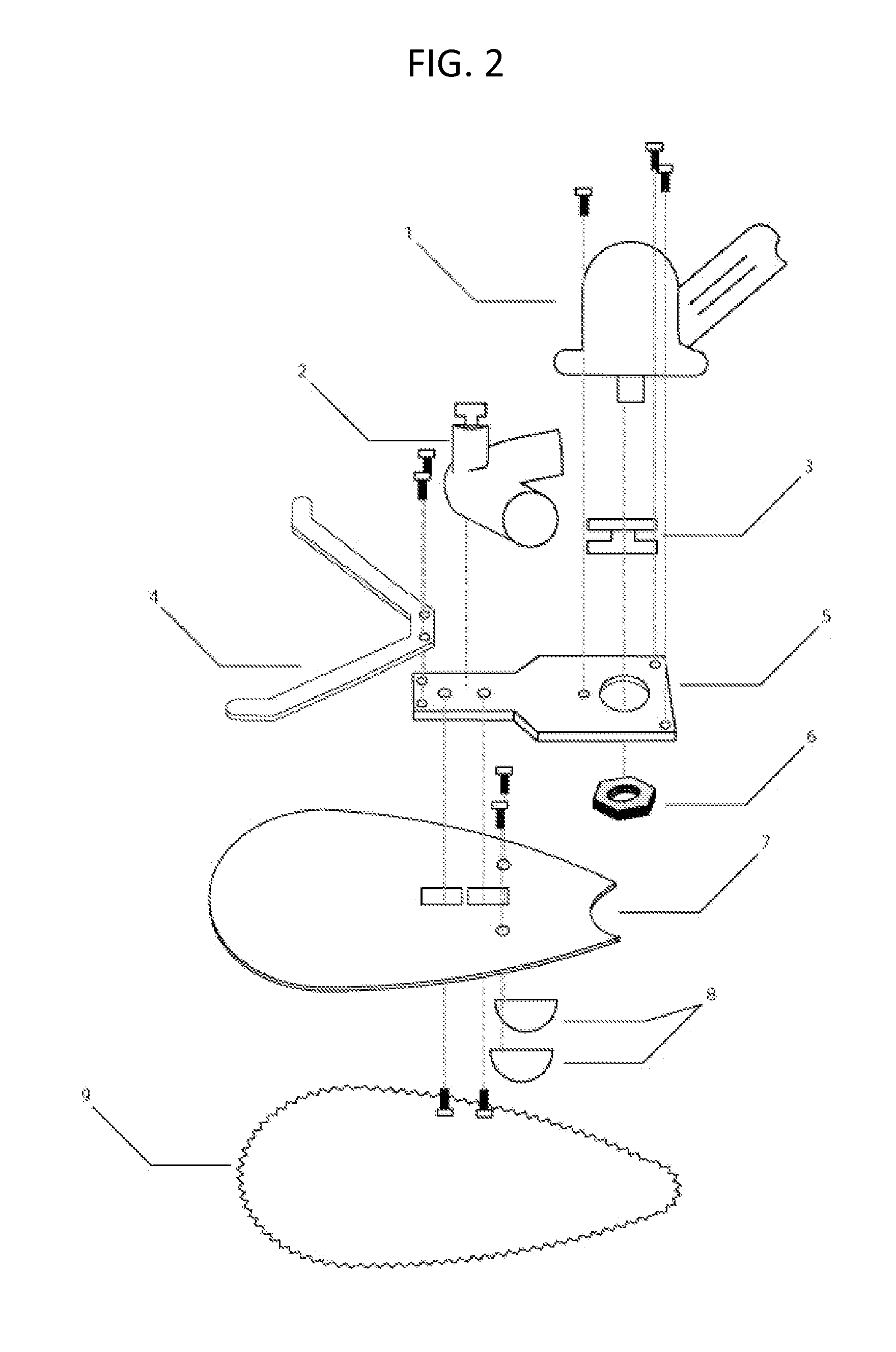
[0011]Referring now to FIG. 2, and in general terms, the invention is comprised of an assembly chassis (5) to which is affix...


PUM

PropertyMeasurementUnit
attitude angleaaaaaaaaaa

Abstract

A brush cutting assembly, horizontally oriented and designed to operate in close proximity to the soil surface for clearing brush and other light vegetation, in the form of a plurality of cutting elements pivotally interconnected with one another forming a cutting span propelled by a motor-driven sprocket and wrapped around the peripheral edge of a relatively thin, generally flat member having a marginal edge portion that engages cutting elements along the cutting span which enters the kerf produced by the chainsaw chain during the operation. Said assembly can be applied to substantially any type of tool which uses a drive member commonly used for clearing weeds and light brush, connected by way of a shaft and an arbor. The preferred embodiment being a hand-held type gasoline powered vegetation trimmer.

Description

BACKGROUND OF THE INVENTION[0001]The invention relates generally to a brush cutting assembly, horizontally oriented and designed to operate in close proximity to the soil surface, for clearing brush and other light vegetation, in the form of a plurality of cutting elements pivotally interconnected with one another forming a cutting span (a “chainsaw chain”, hereinafter) propelled by a motor-driven drive sprocket and wrapped around the peripheral edge of a relatively thin, generally flat member having a marginal edge portion that engages cutting elements along the cutting span which enters the kerf produced by the chainsaw chain during the operation (hereinafter, a “guide bar”). Said assembly can be applied to substantially any type of tool which uses a drive member commonly used for clearing weeds and light brush, connected by way of a shaft and an arbor. The preferred embodiment being a hand-held type gasoline powered vegetation trimmer.[0002]There are innumerous cutting blades and...

Claims


Application Information

Patent Timeline
Patent Type & Authority Applications(United States)
IPC IPC(8): B27B17/08B27B17/12B27B17/02
CPCB27B17/08B27B17/12B27B17/02
Inventor JOYE, DARRELL ANDREW
Owner JOYE DARRELL ANDREW
Why Eureka
Try Eureka