
Novel multiple-pulse surge protection device

A surge protector and multi-pulse technology, which is applied in the field of surge protectors and new multi-pulse surge protectors, can solve the problems that the coordination of energy and time cannot satisfy the suppression of lightning pulses, SPD overheating, explosion and fire, SPD damage, etc. , to achieve the effect of ensuring safe and effective operation, reducing lightning disasters, good economic and social benefits

Active Publication Date: 2014-05-21
FOSHAN SHUNDE LUNJIAO JINDUN LIGHTNING PROTECTIONTECH DEV +1
View PDF6 Cites 3 Cited by
  • Summary
  • Abstract
  • Description
  • Claims
  • Application Information

AI Technical Summary

Problems solved by technology

In order to pass the first-level test, usually the first-level SPD adopts a mixed design of switch and voltage limiting device. This hybrid SPD (T1) has a large flow capacity. However, in addition to the existence of pressure-limiting SPD and switching SPD In addition to its inherent shortcomings, the coordination of its energy and time cannot meet the requirements of suppressing lightning pulses. Not only that, further scientific experiments and lightning protection practices have shown that the method of testing SPD with a single pulse in the lightning high-voltage laboratory is consistent with a real lightning strike The facts of multiple pulses do not match. The tolerance of the SPD tested by the lightning high voltage laboratory with a single pulse is far from its nominal value in real lightning strikes, which often leads to SPD overheating, explosion and fire, causing fire accidents
SPD natural lightning strike tolerance test at Guangzhou Field Lightning Test Base on August 12, 2008: There are 8 times of negative polarity non-single LEMP return strikes, the maximum current is 26.4kA, the maximum current flowing through SPD is 1.64KA, resulting in a nominal current of 20kA The SPD is damaged

Method used


Image

  • Novel multiple-pulse surge protection device
  • Novel multiple-pulse surge protection device

Examples


Embodiment Construction

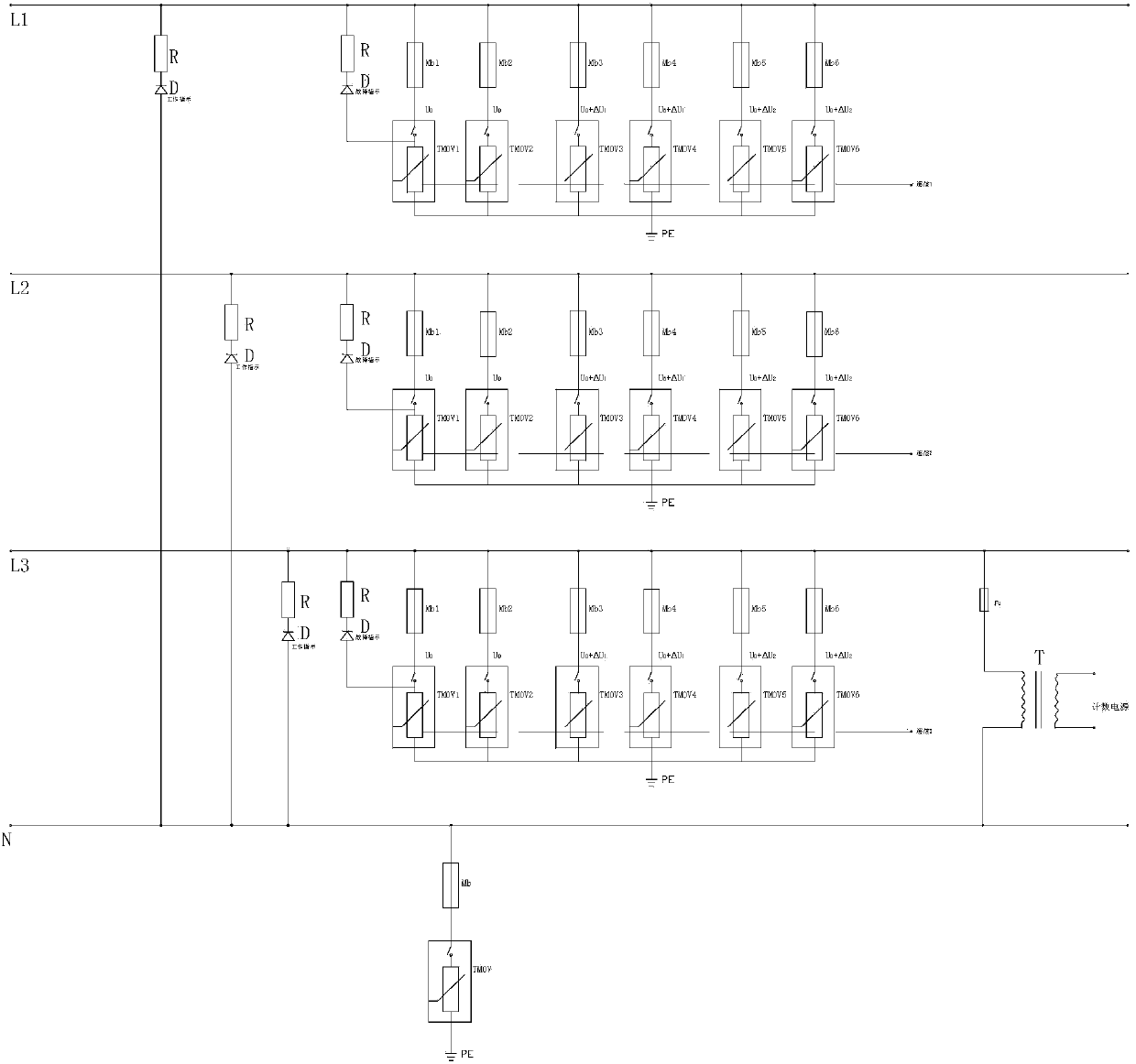
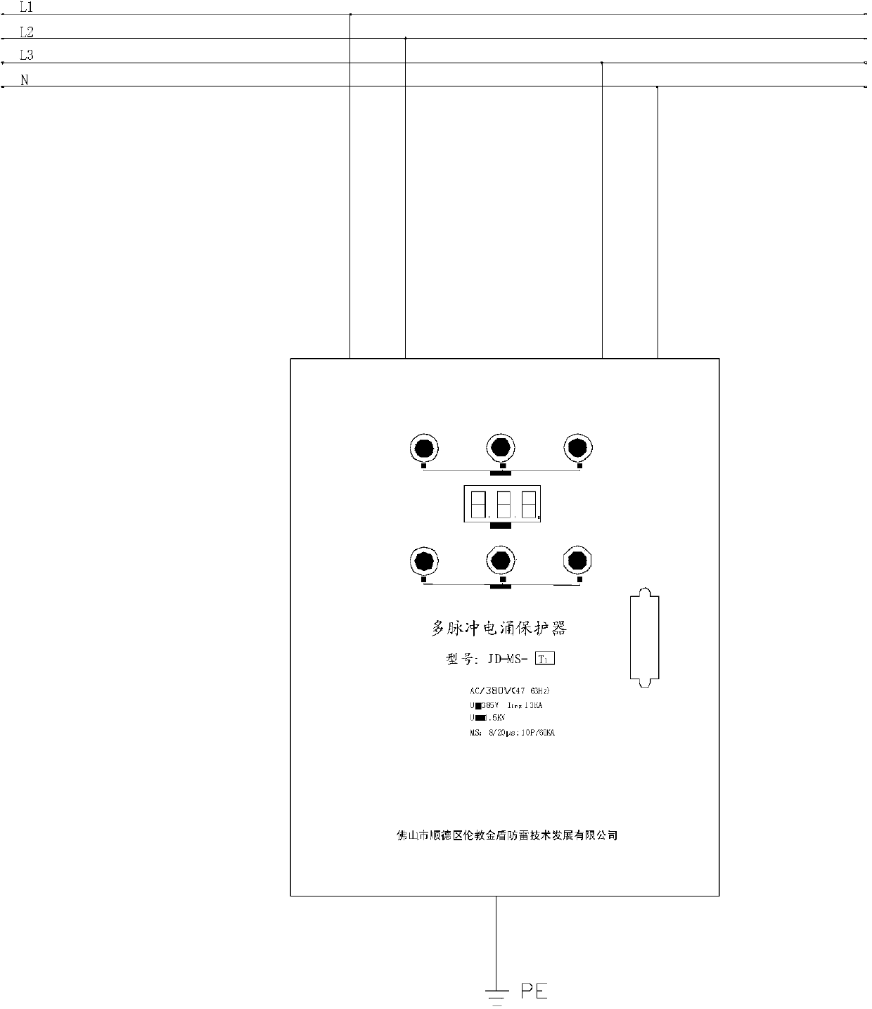
[0023] Such as figure 1 As shown, the new multi-pulse surge protector of the present invention includes a protector body, and a three-phase circuit is arranged in the protector body, and the live wire branch of each phase circuit is provided with six-level multi-pulse current impact voltage limiting Protection circuit, each stage of multi-pulse current impact voltage limiting protection circuit includes a series branch formed by at least one varistor and a pulse fuse, wherein the varistors of the first series branch and the second series branch The DC working voltage is U 0 , the DC working voltages of the varistors in the third series branch and the fourth series branch are U 0 +△U 1 , the DC operating voltages of the varistors in the fifth series branch and the sixth series branch are U 0 +△U 2 .

[0024] Further, the zero line branch of the protector body is also provided with at least one stage of multi-pulse high-current surge voltage-limiting protection circuit, whe...


PUM


Abstract

The invention discloses a novel multiple-pulse surge protection device. The novel multiple-pulse surge protection device comprises a protection device body, a three-phase circuit is mounted in the protection device body, a live wire branch of each phase of circuit is provided with at least six stages of multiple-pulse large current shock pressure limiting protection circuits with standby protection elements, wherein each stage of multiple-pulse large current shock pressure limiting protection circuit comprises a series branch which is composed of at least one voltage dependent resistor and one standby protection element. The novel multiple-pulse surge protection device has advantages that the power frequency short-circuit current is broke directly instead of using a copper block and is capable of bearing multiple pulse impact of real thunder and lightning, and the energy is matched with the time; the novel multiple-pulse surge protection device is capable of passing the primary test T1 and is suitable for the first-stage SPD mounted in the field or in a building to more effectively protect various electric and electronic equipments with low voltage distribution lines.

Description

technical field [0001] The invention relates to a surge protector, which belongs to the technical field of lightning protection equipment, in particular to a novel multi-pulse surge protector. Background technique [0002] With the continuous advancement of science and technology and the continuous development of electronic technology, various advanced electronic products are increasingly widely used in systems in the fields of information industry, transportation, electric power, finance, and chemical industry. With the gradual intelligence of various electrical components in the low-voltage power distribution system, a large number of electronic components with low withstand voltage, high sensitivity and high integration have been selected as a result. However, lightning overvoltage or operating overvoltage often brings fatal damage to these electronic components, making the breadth, depth and frequency of overvoltage damage continue to increase. Therefore, in order to pr...

Claims


Application Information

Patent Timeline
Patent Type & Authority Applications(China)
IPC IPC(8): H02H9/04
Inventor 杨少杰曾一鸣罗四民
Owner FOSHAN SHUNDE LUNJIAO JINDUN LIGHTNING PROTECTIONTECH DEV
Learn More