[0019]The embodiments of the invention with further developments described in the following are to be regarded only as examples and are in no way to limit the scope of the protection provided by the claims. The arrangement is suitable for all kinds of vehicles, but a truck is used to exemplify the arrangement.
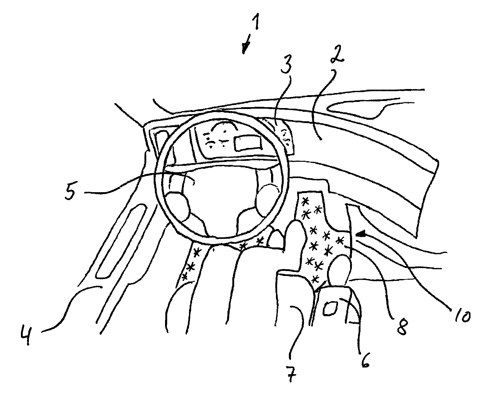
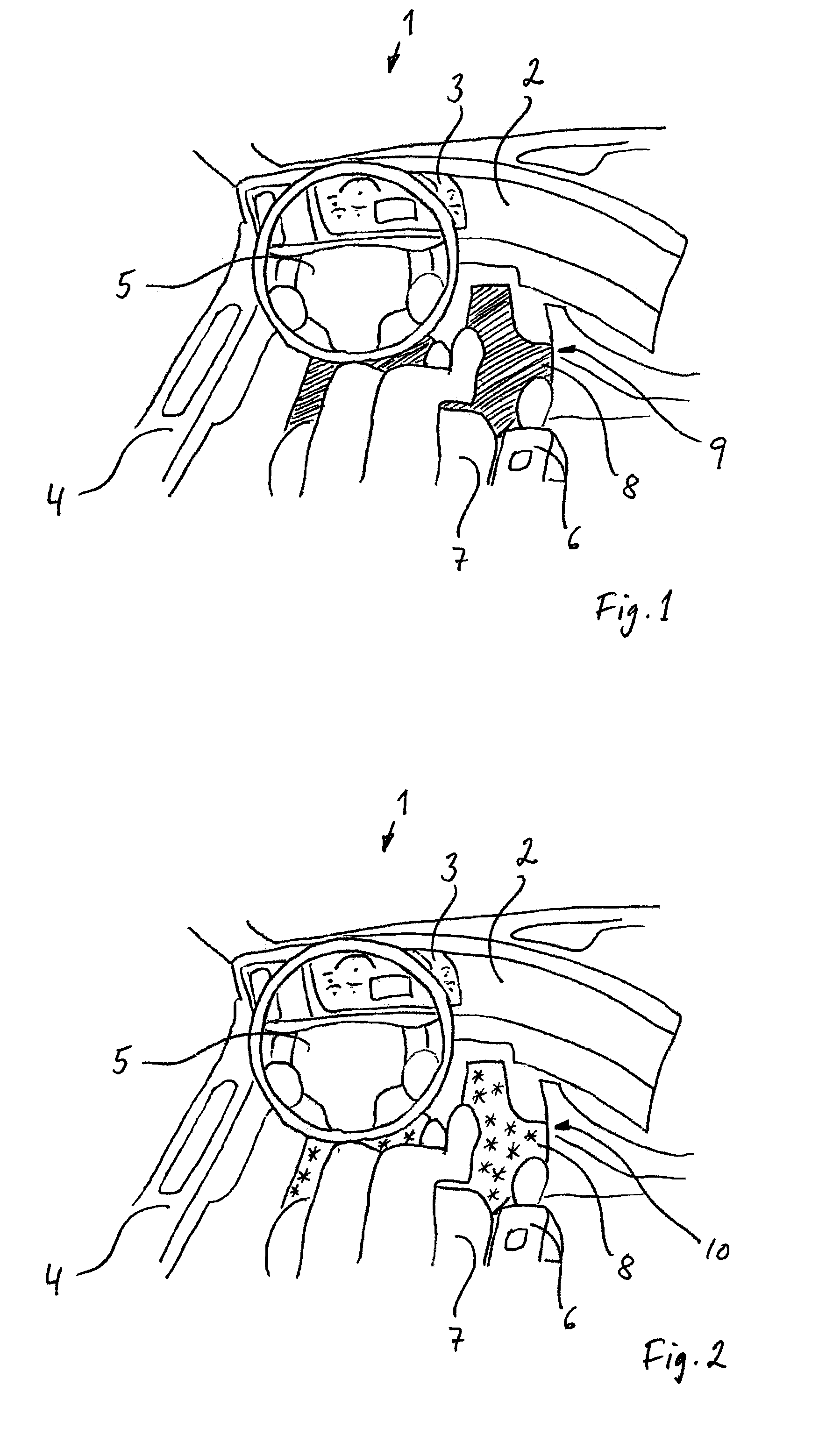
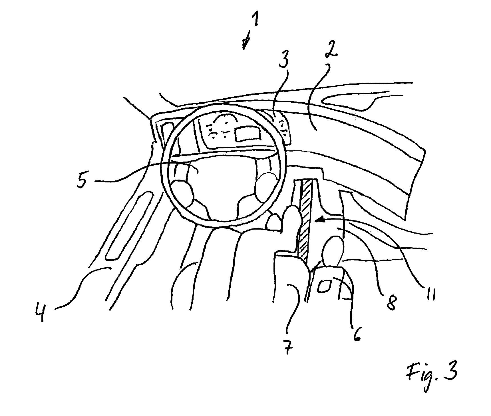
[0020]FIG. 1 shows a schematic view of a driver compartment of a truck with a first example of the inventive arrangement. The driver compartment 1 comprises an instrument panel 2 with an instrument cluster 3, a door panel 4, a steering wheel 5, a gear shift lever 6, a seat 7 and a floor mat 8. Further, the legs of the driver are shown. The floor mat 8 comprises a textile which is capable of displaying an information image, a so called smart textile. The information 9, 10, 11 is thus displayed on the floor of the vehicle.
[0021]There are different types of smart textiles known. One type is based on Electroluminescence materials (EL), which converts electrical energy into light without the generation of heat. Electroluminescence is an optical and electrical phenomenon in which a material emits light in response to the passage of an electric current to a strong electric field. The excited electrons release their energy as photons, i.e. as light. An EL-wire is a light emitting capacitor. The capacitive structure is developed with the light emitting electroluminescent semiconductor layers sandwiched between two conductive electrodes. An EL panel is basically the same material as EL-wire but in the shape of a flat sheet. An electroluminescent panel is paper thin, flexible and light-weight and is available in a wide range of colors, it can dim or flicker. Some EL-wires can change from one color to another (e.g. green to blue) depending on the current given. The wire is also LTV-resistant. The wire emits no heat.
[0022]Another type is known as photonic textiles, which are fabrics that contain lighting systems and can therefore serve as displays. This is done by integrating flexible arrays of multicoloured light-emitting, diodes (e.g. OLEDs) into fabrics and doing so without compromising the softness of the cloth.
[0023]Current photonic textiles are either based on integrating standard components such as LEDs with conductive yarns inside the textile or developing optoelectronic devices with a fibre form factor, such as photo luminescent polymer-coated fibres, surface- or side-emitting fibres or yarns coated with thermo-chromic ink, that can be integrated directly into textile structures.
[0024]The advantage of OLEDs, in comparison to the LEDs that are often used in textiles, is the emission of homogenous light over a larger surface area. In addition feedback from designers shows that photonic systems enabled by OLEDs are aesthetically more pleasing than LED-based enhanced textiles that must be covered by additional textile optical diffuser layers. Compared to other fibre-based photonic systems such as textiles fabricated from photo luminescent, thermo-chromic, or optical fibres, OLEDs have higher light intensities. And finally, OLEDs are also lightweight, have a flat form factor, and can be flexible if fabricated on a polymer foil substrate.
[0025]By using a smart textile on the floor of the vehicle, information can be displayed to the driver by the smart textile. InFIG. 1 , the floor mat 8 comprises a smart textile adapted to display a specific colour when a specific event occurs. In this example, the information is displayed as a specific colour 9 on the complete floor mat surface.
[0026]One such event may be the temperature of the road. If the temperature is close to freezing, the low temperature condition can be shown by lighting the textile with a colour indicative of low temperature, e.g. by using an ice blue colour. It is further possible to vary the intensity of the colour in dependency of the actual ambient temperature or by the actual temperature of the road, such that the light is dim at a temperature of e.g. 6 degrees centigrade and that the light lights with full intensity at e.g. 2 degrees centigrade. Depending on the type of smart textile used, other colours such as white may also be used to indicate a low temperature.
[0027]In FIG. 2, another example of a low temperature warning is shown. Here, the information is displayed as snowflakes 10 on the floor by the smart textile, which will also give the driver a low temperature warning. The intensity of the snowflakes may vary with the actual ambient temperature, or the size of the snowflakes may vary with the actual temperature. It is also possible to let the colour of the snowflakes vary in dependency of the actual ambient temperature.
[0028]In FIG. 3, to further example of information which is display by the inventive arrangement is shown. In this example, information regarding the road marking lines is displayed. The information is preferably displayed as a line 11 on the floor, preferably corresponding, to the position of the actual position of the road marking line on the road underneath the vehicle. In this way, the driver will receive information of the exact location of the road marking line when a road marking, line is being passed by the vehicle, e.g. during a lane change. If the lane change is unintentional, e.g. if the driver passes the road marking line without using the flasher, it is possible to flash the line displayed on the floor, in order to give the driver a warning.
[0029]The invention is not to be regarded as being limited to the embodiments described above, a number of additional variants and modifications being possible within the scope of the subsequent claims.