Gripping Glove

a glove and glove technology, applied in racket sports, protective garments, garment special features, etc., can solve the problems of user's hand being injured, user's hand must exert maximum gripping effort, vibration, etc., to enhance the biomechanical functions and capabilities improve the grip of the user's hand, and reduce or eliminate the effect of rotational forces

Active Publication Date: 2015-11-05
BAILEY CLAIBORNE
View PDF6 Cites 17 Cited by
  • Summary
  • Abstract
  • Description
  • Claims
  • Application Information

AI Technical Summary

Benefits of technology

[0003]This disclosure generally relates to a glove for the human hand which may be worn to improve a user's grip on an item. In some implementations, this disclosure describes an improved gripping glove as it relates to a swingable tool with a rigid handle (i.e., cylindrical, elliptic cylinder, polyhedral cylinder with n-gonal sides, or the like) such as a hammer, ax, shovel, baseball bat, softball bat, golf club, oar, paddle, or the like. Furthermore, this disclosure relates to a gripping aid which may act as a shaped support along a portion of the thumb webbing on the palmar side of a hand that may enhance biomechanical functions and capabilities of the user's hand while gripping. In some implementations, the gripping aid integrated with the glove may be a continuous piece of material from a joint on a first digit (e.g., thumb) of a hand to a joint on a second digit (e.g., index finger) of the hand. In some implementations, the gripping aid may act as a shaped support which may be a crush resistant compound such a silicon rubber, ethylene propylene rubber, or the like. In some implementations, the shaped support may provide a buffer zone to help position the tool away from a portion of the hand. In this instance, the gripping aid may reduce or eliminate the rotational forces upon the hand as the tool is manipulated and, ultimately, reduce or eliminate the incidence of superficial skin trauma (e.g., abrasions and / or blisters) to the hand.
[0004]Furthermore, this disclosure describes a gripping aid that places the hand in the optimal gripping position by increasing the grip span, which enhances grip strength. Additionally, in some implementations, this disclosure describes the gripping aid which may also include a crest (i.e., pivot ridge, crown, or fulcrum) that allows the hand to more efficiently and effectively manipulate the tool as it is swung. For instance, the crest may act to speed the centripetal force of a distal end of tool as the user grips and swings a proximal end of the tool. In some implementations, the crest shape of the gripping aid may increase momentum or torque of the tool as it is swung and thus lower the moment of inertia without reducing the power created by the swing. In this instance, the gripping aid may help maximize the efficiency and / or speed of each swing of the tool. As such, the gripping aid described herein may increase output forces upon the tool, enhance comfort, reduce grip tension, reduce vibration, and reduce overall fatigue of a user swinging the tool. In other implementations, the gripping aid described herein may be used independently of other aids or as an integral part of other gripping aids, for example gloves.

Problems solved by technology

Human hands are used to accomplish many tasks and therefore are susceptible to vibration, bone bruises, blisters, fatigue, and / or other discomfort.
In these instances, because of the lack of support within the thumb web area of the hand, the user must exert maximum gripping effort with their hand(s) to properly control the tool.
However, such maximum gripping effort may result in various injuries to the hand such as blisters and / or bruises caused by vibrations transferred to the hand when the tool contacts an object (tree, nail, ball, or the like).
Furthermore, the generally round diameter of tool handles for multiple tool applications does not provide an ideal shape for maximizing grip span and / or user comfort.
In addition, round handle shapes do not provide the ideal leverage point needed for maximizing the efficiency, control, power, speed, and / or strength of a user manipulating the tool.

Method used


Image

  • Gripping Glove
  • Gripping Glove
  • Gripping Glove

Examples


example environment

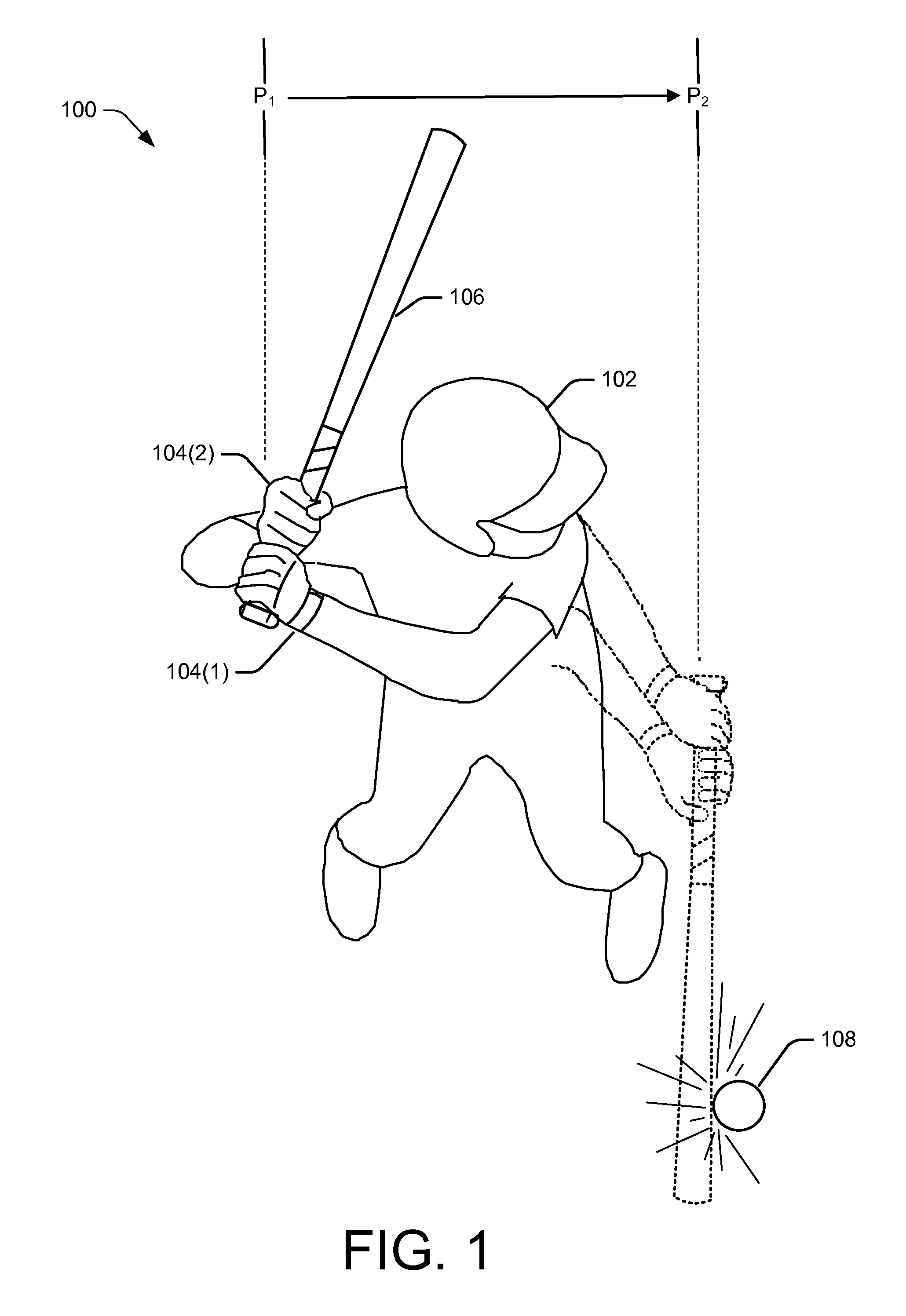
[0034]FIG. 1 illustrates an example environment 100 for the use of the gripping glove. FIG. 1 shows a user 102, such as a batter, wearing gripping gloves 104(1) and 104(2) on a left and right hand, respectively. As shown, the user 102 is also holding a bat 106 at a position P1 corresponding to a set, ready position prior to starting a swing. In other implementations, depending on the user preference and / or application of the gripping glove, the user 102 may wear a glove on only one hand.

[0035]In initiating a typical swing of the bat 106 (shown at P1), the user 102 manipulates his / her body by rotating his / her hips, spine, shoulders, and arms to move the hands toward the object intended to be struck (e.g., baseball 108). Such rotation generates significant centripetal force at the distal end of the bat 106 (i.e., the bat head). Generally, the amount of force generated during this rotation will be translated into a power at the contact point of the baseball 108 (shown at P2).

[0036]Whil...

example gripping glove

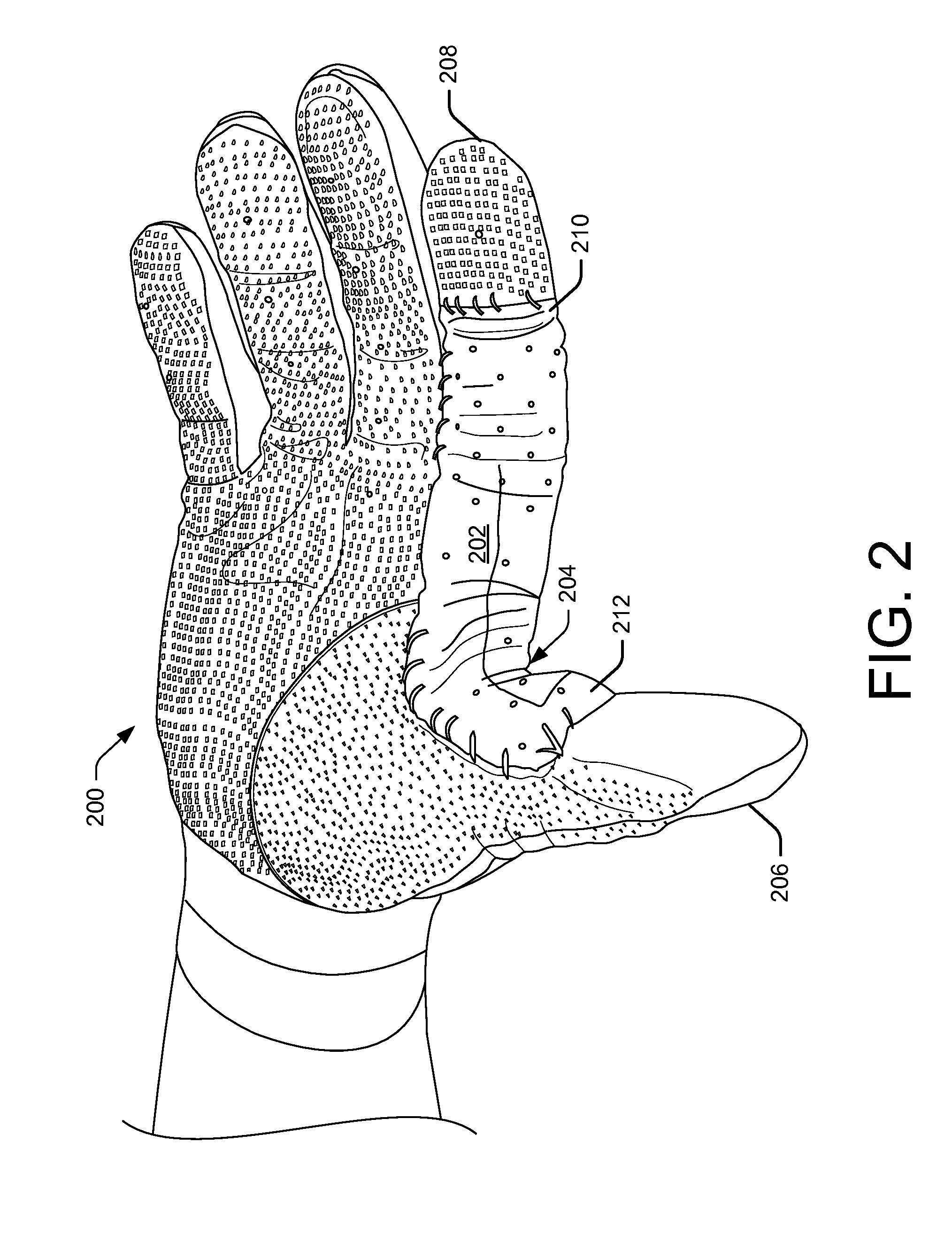
[0039]FIGS. 2-13 illustrate example embodiments or example components of a gripping glove. FIG. 2 illustrates an example embodiment of the gripping glove (hereinafter, “glove”) 200. As shown, glove 200 is placed on a right hand of a human. However, in other embodiments, the glove 200 (or any other glove described herein) may be configured to be placed on a left hand of a human.

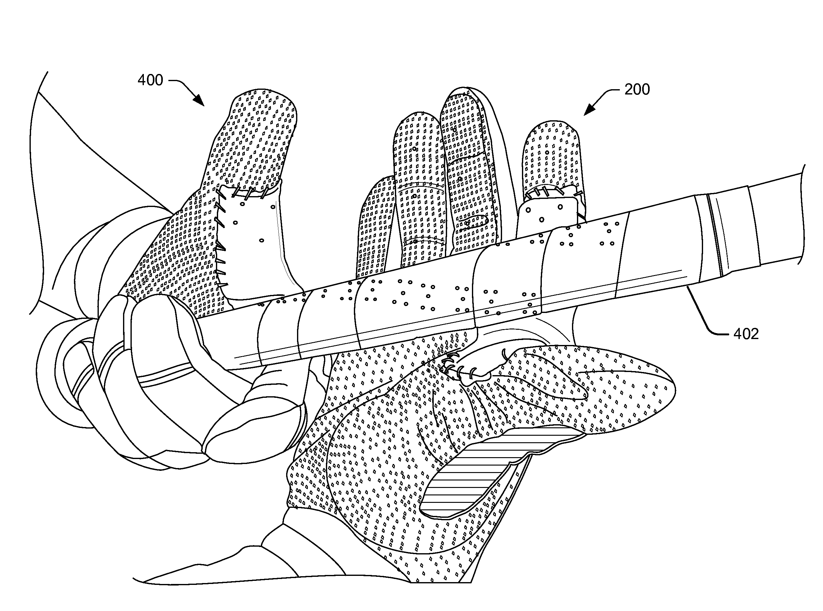
[0040]FIG. 2 illustrates that a gripping aid 202 may be place along the thumb webbing 204 between the thumb 206 and index finger 208. As shown, the gripping aid 202 may form a continuous support along the thumb webbing 204 from a first end 210 beginning on the index finger 208 at the distal interphalangeal (DIP) joint to the second end 212 on the thumb at the interphalangeal (IP) joint of the thumb. In other implementations, the first end 210 may begin at the proximal interphalangeal (PIP) joint of the index finger 208.

[0041]As shown, the gripping aid may be secured to the glove 200 by placing one or more piec...

example process

[0069]FIG. 15 illustrates an example process 1500 for assembling an example gripping glove as described above. The process 1500 is illustrated as a logical flow graph. The order in which the operations or steps are described is not intended to be construed as a limitation, and any number of the described operations can be combined in any order and / or in parallel to implement the process 1500.

[0070]The process 1500 for assembling a gripping glove begins at 1502 where a size of a glove may be determined. As described above, the gripping glove may be constructed in numerous sizes to fit various sizes of a human hand (e.g., extra-small, small, medium, large, and extra-large, etc).

[0071]At 1504, a gripping aid may be determined. In some implementations, the determination of the gripping aid may be based on the determined size of the glove. In some implementations, the determining the gripping aid may further comprise determining the size and / or shape (e.g., thickness, taper, crest profil...


PUM


Abstract

This disclosure describes a gripping glove with a gripping aid to increase the grip span of a user. In some implementations, the gripping aid may be composed of a crush resistant, flexible material and further include a crest or fulcrum to increase the speed, strength and/or torque of each swing of a tool (e.g., a baseball bat, sledge hammer, or the like). In some implementations, the gripping aid may also provide a reduction in vibrations and superficial hand traumas normally caused when the tool strikes an object.

Description

CROSS REFERENCE TO RELATED APPLICATION[0001]This application claims priority under 35 U.S.C §119 to U.S. Provisional Patent Appln. No. 61 / 986,965 filed May 1, 2014, entitled “Improved Gripping Glove,” the entirety of which is incorporated by reference in its entirety.BACKGROUND[0002]Human hands are used to accomplish many tasks and therefore are susceptible to vibration, bone bruises, blisters, fatigue, and / or other discomfort. This is particularly true when a user must grip and manipulate a tool with a handle (e.g., ax, hammer, shovel, baseball / softball bat, lacrosse stick, rowing oar, or the like). In these instances, because of the lack of support within the thumb web area of the hand, the user must exert maximum gripping effort with their hand(s) to properly control the tool. However, such maximum gripping effort may result in various injuries to the hand such as blisters and / or bruises caused by vibrations transferred to the hand when the tool contacts an object (tree, nail, ba...

Claims


Application Information

Patent Timeline
Patent Type & Authority Applications(United States)
IPC IPC(8): A41D19/015A63B71/14
CPCA63B71/143A41D19/01564A63B71/146A63B2209/00A63B60/54A63B71/148A41D2400/80A41D2600/10A41D2600/20
Inventor BAILEY, CLAIBORNE
Owner BAILEY CLAIBORNE
Why Eureka
Try Eureka