Machine and Method for Additive Manufacturing

a technology of additive manufacturing and machine, applied in the direction of auxillary welding devices, additive manufacturing processes, soldering apparatus, etc., can solve the problem of stained inside the shaping chamber, and achieve the effect of preventing unsolidified powder samples

Inactive Publication Date: 2015-11-05
JEOL LTD
View PDF0 Cites 42 Cited by
  • Summary
  • Abstract
  • Description
  • Claims
  • Application Information

AI Technical Summary

Benefits of technology

[0019]In the three-dimensional additive manufacturing device with the above-described configuration, the shaping box is detachably supported by the box support body and thus, it can be removed from the box support body in a state in which the shaped object and the powder sample are accommodated. As a result, the shaped object can be taken out of the shaping chamber without pushing out the completed shaped object from the shaping box.
[0023]According to the three-dimensional additive manufacturing device and the three-dimensional additive manufacturing method of the present invention, it is possible to prevent unsolidified powder sample from staining the inside of the shaping chamber.

Problems solved by technology

However, in the prior-art three-dimensional additive manufacturing device, when the completed shaped object is to be taken out, since the stage is raised and the shaped object is taken out of the pit of the shaping frame in the shaping chamber, an unsolidified powder sample (hereinafter referred to as an “unnecessary powder”) M2 adhering to the periphery of the shaped object P1 is also pushed out of the pit.
As a result, there is a problem that an inside of the shaping chamber is stained by the unnecessary powders pushed out of the pit.

Method used


Image

  • Machine and Method for Additive Manufacturing
  • Machine and Method for Additive Manufacturing
  • Machine and Method for Additive Manufacturing

Examples


first embodiment

1. First Embodiment

[0043]1-1. Configuration of Three-Dimensional Additive Manufacturing Device

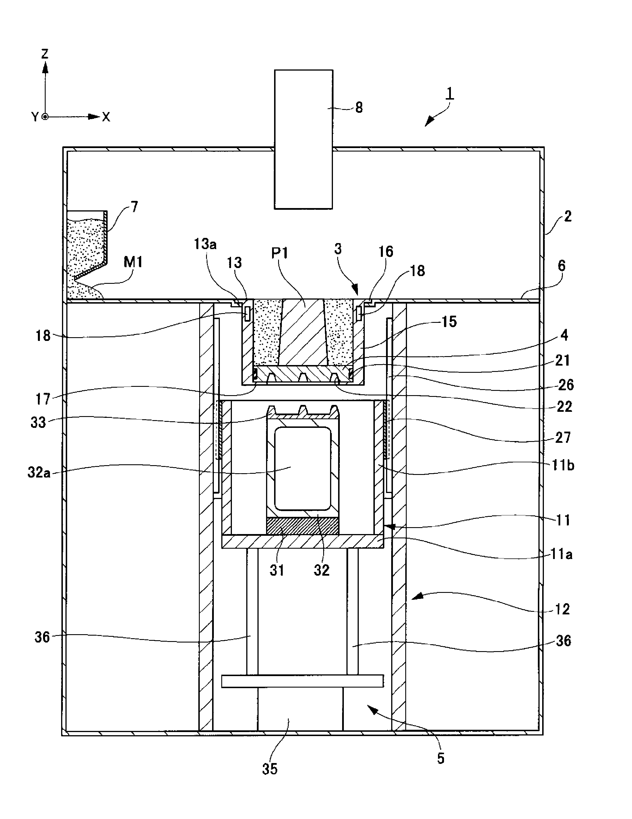
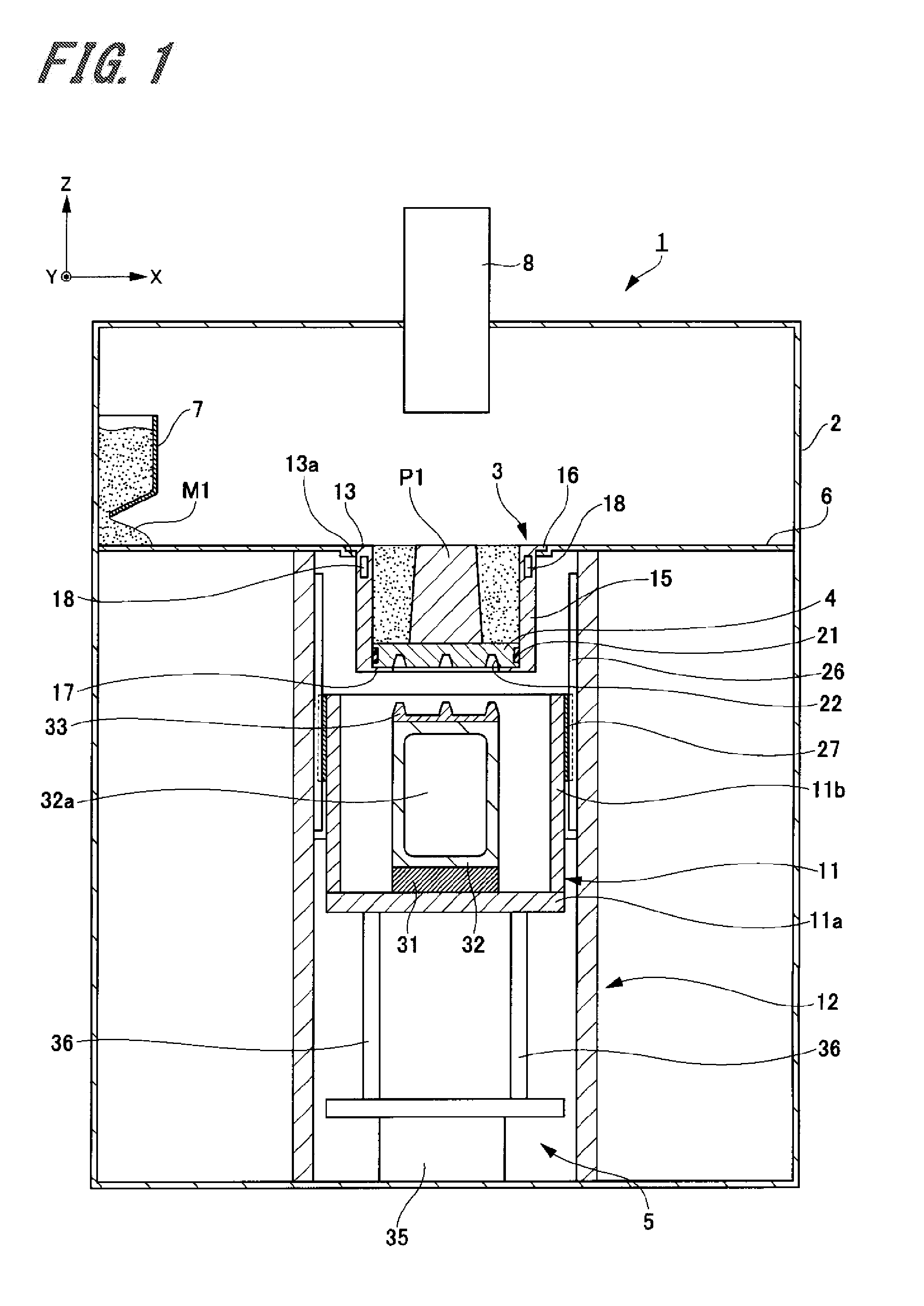
[0044]First, a first embodiment of a three-dimensional additive manufacturing device of the present invention will be described by referring to FIG. 1.

[0045]FIG. 1 is a schematic sectional view schematically illustrating the three-dimensional additive manufacturing device of this embodiment.

[0046]A three-dimensional additive manufacturing device 1 illustrated in FIG. 1 is a device for shaping a three-dimensional object by irradiating a powder sample made of metal powders such as titanium, aluminum, and iron, for example, with an electron beam to melt the powder sample, and by laminating layers in which this powder sample is solidified.

[0047]The three-dimensional additive manufacturing device 1 has a hollow shaping chamber 2, a shaping box 3, a stage 4, a stage moving mechanism 5 for movably supporting the stage 4, a box support body 6 for detachably supporting the shaping box 3, a powder la...

second embodiment

2. Second Embodiment

[0082]Subsequently, a second embodiment of the present invention will be described by referring to FIGS. 3 to 11.

[0083]FIG. 3 is an explanatory view schematically illustrating a three-dimensional additive manufacturing device.

[0084]2-1. Configuration and Operation of Second Embodiment

[0085]A three-dimensional additive manufacturing device 50 according to this second embodiment is different from the three-dimensional additive manufacturing device 1 according to the first embodiment in a point that a treatment chamber for performing secondary processing on the completed shaped object P1 is made adjacent to the shaping chamber. Thus, here, the shaping chamber, the treatment chamber, and the conveying mechanism will be described, and the same reference numerals are given to common portions to those of the three-dimensional additive manufacturing device 1 according to the first embodiment, and duplicated explanation will be omitted.

[0086]As illustrated in FIG. 3, the ...

third embodiment

3. Third Embodiment

[0125]Subsequently, a third embodiment of the present invention will be described by referring to FIG. 12.

[0126]FIG. 12 is an explanatory view illustrating a three-dimensional additive manufacturing method according to the third embodiment.

[0127]This third embodiment relates to a three-dimensional additive manufacturing method, and a constitution of a three-dimensional additive manufacturing device is similar to those of the three-dimensional additive manufacturing device 1 according to the first embodiment and the three-dimensional additive manufacturing device 50 according to the second embodiment. Thus, for the constitution of the device, here, the three-dimensional additive manufacturing device 50 according to the second embodiment will be used for describing only its three-dimensional additive manufacturing method.

[0128]As illustrated in FIG. 12, in the three-dimensional additive manufacturing method according the third embodiment, first, the shaped object P1...


PUM

PropertyMeasurementUnit
two-dimensional structureaaaaaaaaaa
heightaaaaaaaaaa
thicknessaaaaaaaaaa

Abstract

To provide a three-dimensional additive manufacturing device and a three-dimensional additive manufacturing method in which a completed shaped object can be taken out without staining a shaping chamber.A three-dimensional additive manufacturing device 1 includes a shaping chamber 2, a shaping box 3, a stage 4, and a box support body 6. The shaping box 3 accommodates a shaped object P1 and a powder sample M1 for forming the shaped object. The box support body 6 is provided inside the shaping chamber 2 and detachably supports the shaping box 3.

Description

CROSS REFERENCES TO RELATED APPLICATIONSBACKGROUND OF THE INVENTION[0001]1. Field of the Invention[0002]The present invention relates to a three-dimensional additive manufacturing device which laminates and shapes layers in each of which a powder sample is thinly spread one by one on a stage and a three-dimensional additive manufacturing method.[0003]2. Description of the Related Art[0004]Recently, a three-dimensional additive manufacturing technology for laminating and shaping layers in each of which a powder sample is thinly spread one by one attracts attention, and many types of three-dimensional additive manufacturing technologies have been developed due to differences in materials of the powder samples and shaping methods.[0005]As a shaping method of prior-art three-dimensional additive manufacturing devices, a powder sample is spread, on an upper surface of a stage which is a powder table for each layer, for example. Subsequently, in the powder sample spread on the stage, only...

Claims


Application Information

Patent Timeline
Patent Type & Authority Applications(United States)
IPC IPC(8): B23K15/00B23K37/04B23K26/34
CPCB23K15/0086B23K26/345B33Y30/00B33Y10/00B23K37/04B29C64/153B29C64/35B33Y40/20B29C64/25B29C64/379B29C64/232Y02P10/25B22F10/28B22F12/82B22F12/22B22F12/41B22F12/222B22F12/86B22F10/47
Inventor YAMADA, MASAHIRO
Owner JEOL LTD
Why Eureka
Try Eureka