Air Chamber Hull

a technology of air chamber and hull, which is applied in the direction of special purpose vessels, marine propulsion, vessel construction, etc., can solve the problems of large cargo ships traveling in the open ocean with large waves, uncomfortable and unsafe riding conditions, and not meeting the criteria of cost and power us

Inactive Publication Date: 2015-11-05
JACKSON ORIN
View PDF2 Cites 8 Cited by
  • Summary
  • Abstract
  • Description
  • Claims
  • Application Information

AI Technical Summary

Problems solved by technology

Water displacement and water friction of marine vessels accounts for some of the biggest costs and power uses required to drive a vessel through water.
If the water waves are large the boat tends to bounce up and down and bang into oncoming large waves causing a very uncomfortable and unsafe riding condition.
Planing hulls generally only work in lightweight high-speed boat designs used over fairly smooth water.
Large cargo ships traveling in the open-ocean with large waves do not fit these criteria.
By design, these strategies use large water-hull interface, which increases water friction on the vessel.
However, while thin air cavities have been successfully used to reduce water friction, the use of vessels having air cavities that provide a substantial reduction in water displacement has been met with many challenges, in-part due to the limited acceptable environments for vessel, namely calm and flat sea.
In spite of its history, few implementations have been deemed practical and made into the marine vessel industry.
Air cavity hulls add a layer of sophistication and complication as well as additional cost to boat construction.
In sea conditions that present waves, vessels with air cavities that substantially reduce water displacement (rather than merely configured for -friction reduction) often rapidly lose air, e.g. when wave undulation causes a portion of the hull become to airborne.
Further, these air cavities offer negligible capacity for shock absorption and still experience rapid air loss in larger waves.
Lang et al. do not teach a deep air chamber (e.g. a high aspect ratio chamber) configured to reduce water displacement and provide shock absorption.
Further Lang et al. do not teach fins extending from the side walls of an air cavity or air chamber such as inner fins or outer fins.
Further, Lang et al. do not teach elongated fins.
Further, Lang et al. do not teach a wave piercing bow.
Further, Lang et al. do not teach a recirculating air chamber,
Among features, Maloney et al. do not teach a deep air chamber (e.g. a high aspect ratio chamber), stable fore and aft air chamber walls, elongated fins, fins extending laterally from the sidewalls, neutral fins, a recirculating air chamber, or a wave-piercing bow.

Method used


Image

  • Air Chamber Hull
  • Air Chamber Hull
  • Air Chamber Hull

Examples


example 1

Air Cushion Hull with a HAR Air Chamber, Stable Walls, Keel Fins, Wave-Piercing Bow

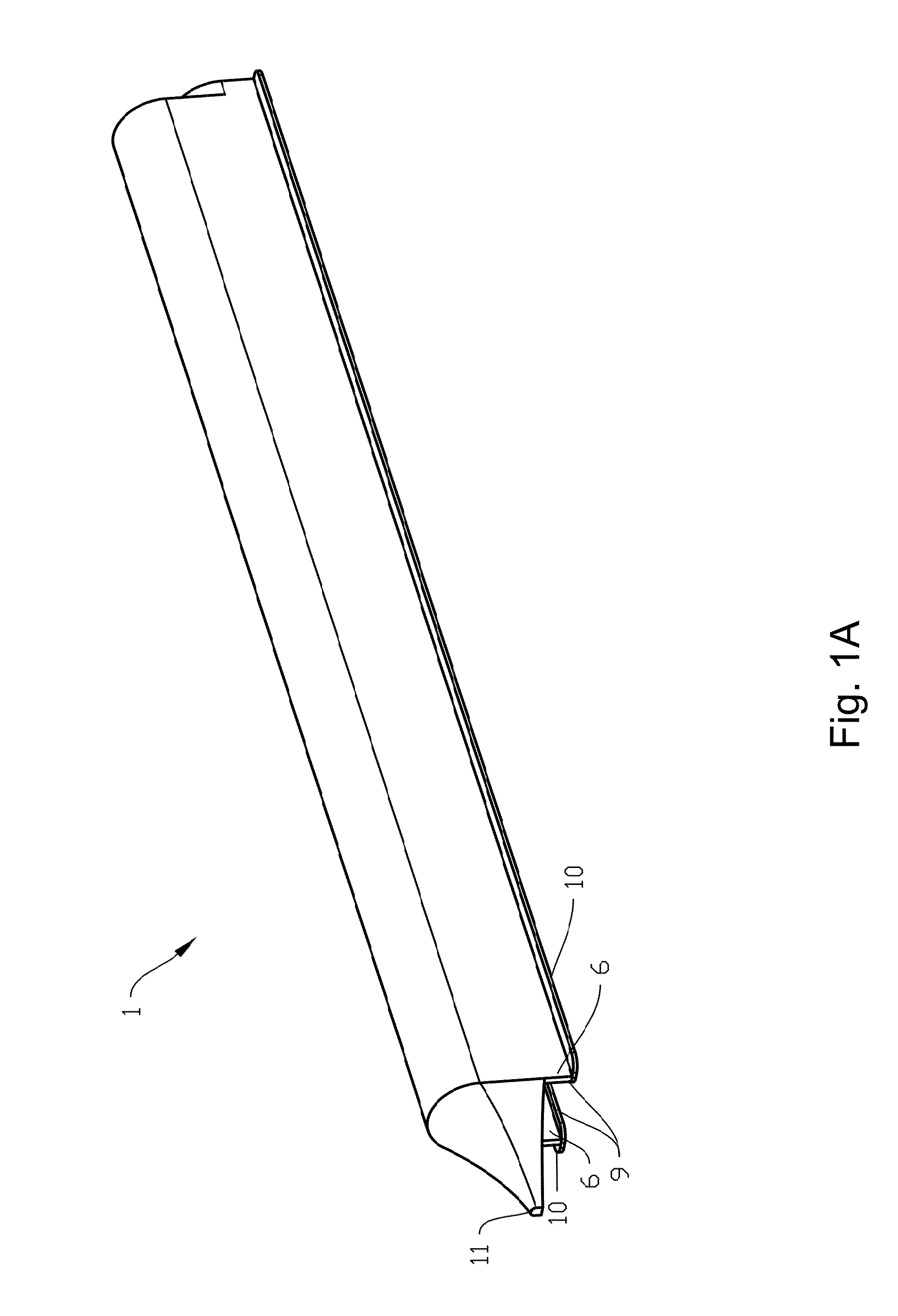
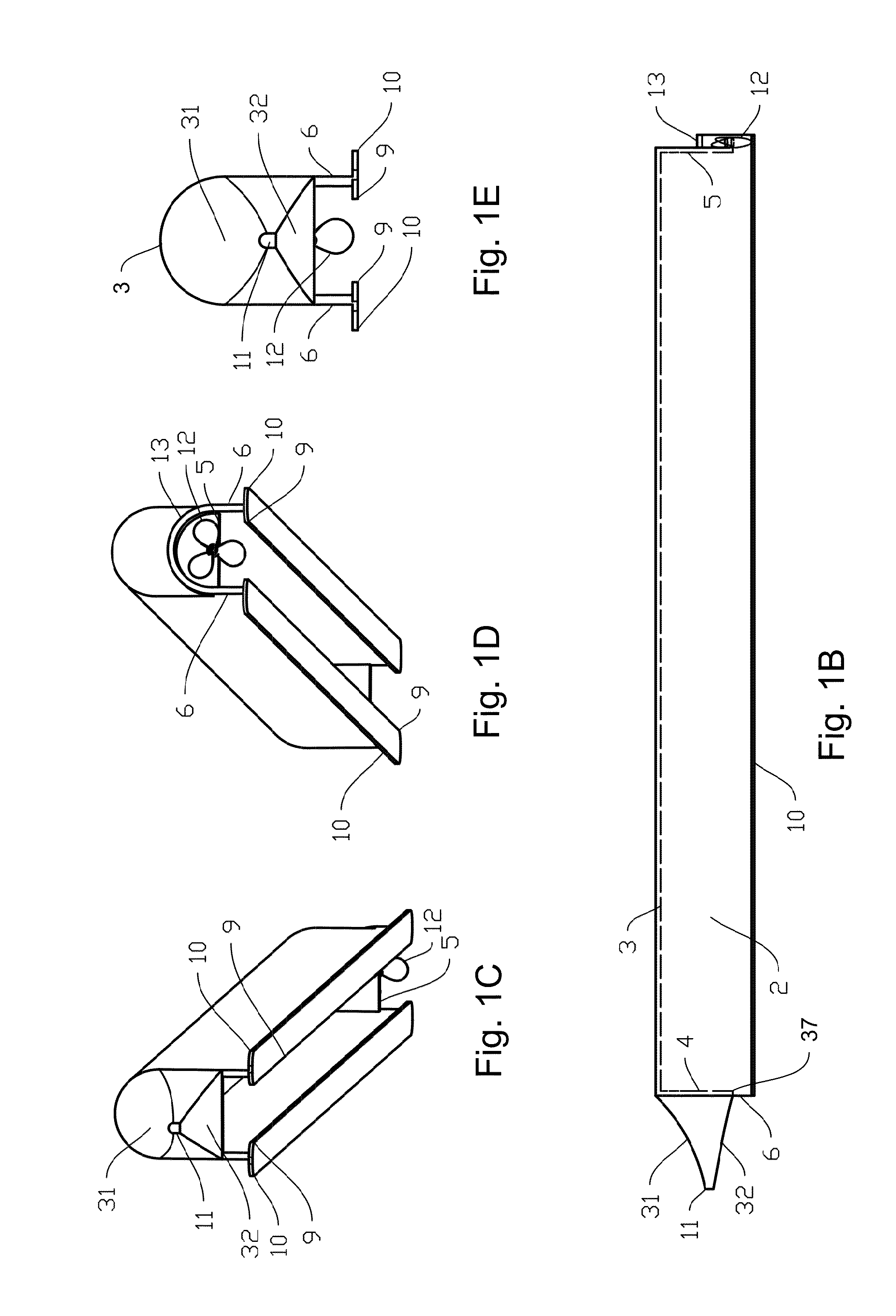
[0206]FIG. 1A-FIG. 1D depict a hull of the invention. The hull comprises an air chamber 2 defined by a fore wall 4, an aft wall 5, an upper wall 3, and opposing sidewalls 6. The foe wall 4 and aft wall 5 are both stable, non-retractable wall. Air injector ports (not shown) are configured to deliver pressurized air to the air chamber to impart an air cushion.

[0207]The sidewalls 6 extend lower than the fore wall 4 and the aft wall 5. The hull comprises fins at the base of each side wall 6 (‘keel fins’). The keel fins are elongated fins that span a greater longitudinal distance (e.g. the entire length of the side wall) than a lateral distance. Specifically, an inner keel fin 9 extends laterally inward from the base of each side wall 6 and an outer keel fin 10 extends laterally outward from the base of each sidewall. The keel fins 9,10 run longitudinally along the entire length of each sidewall 6.

[0208]Th...

example 2

Hull with Recirculating Air Flow

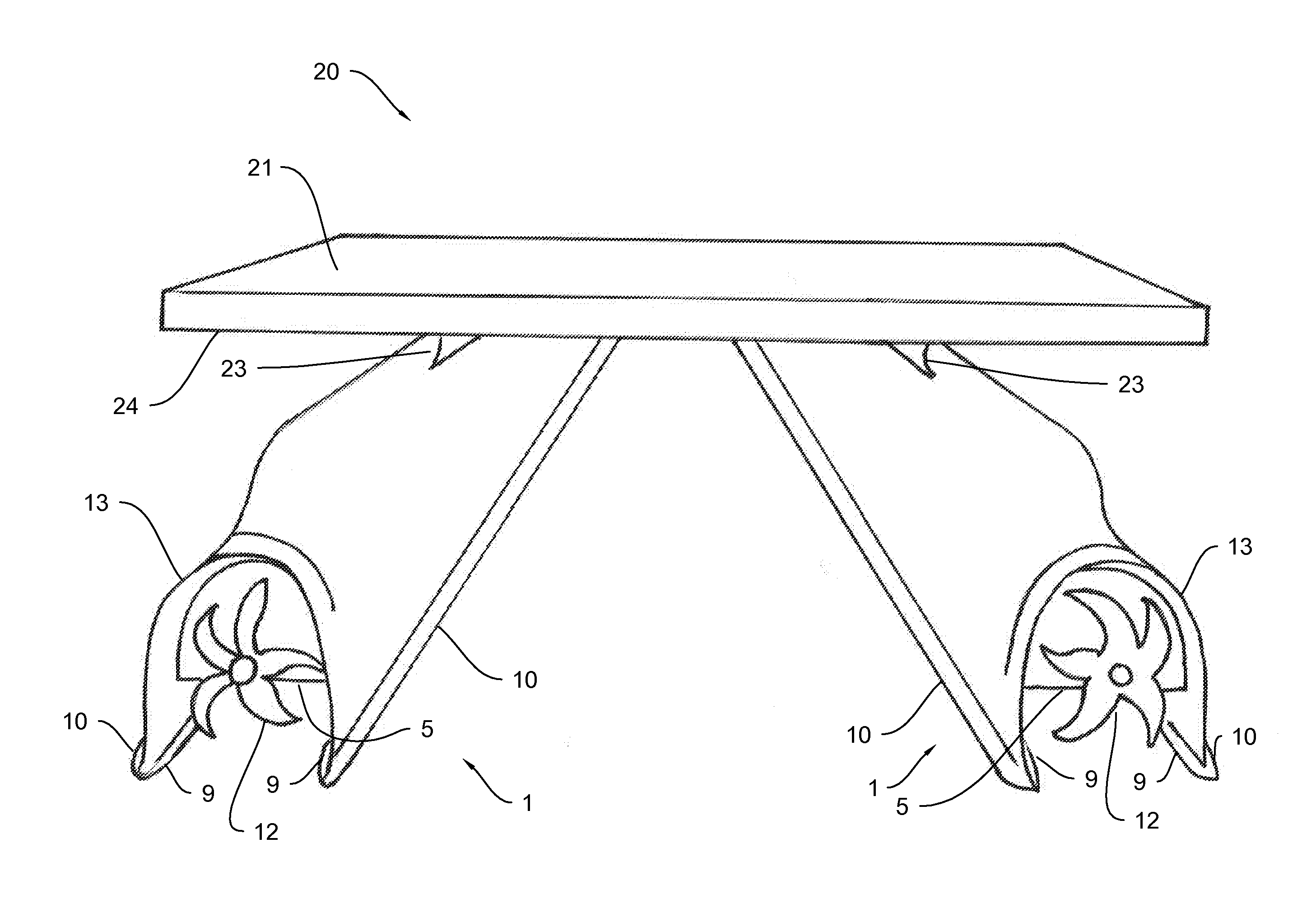
[0211]FIG. 2A-D depict water vessel comprising a deck 20 having top 21, and further comprising a hull 1 of the invention, e.g. as detailed in Example 1, configured with an air chamber 2 having recirculating air flow. The hull comprises an air injector 7 positioned about the base of fore wall 4 aimed astern. The fore wall 4 and the aft wall 5 are both curved and / or provided with a ramped section at the base and upper edges. Such a configuration imparts air flow 33 which travels astern just above the water surface 28 in the air chamber 2 until it reaches the base of the curved aft wall 5, where it ramps up the curve and is redirected forward along the upper wall 3 before reaching the curved fore wall 4, which redirects the air flow 33 back into the path of the air injector 7. Optionally, the hull comprise a second air injector 8 positioned about the upper wall 3 and aimed forward to enhance the recirculating motion of the air 33.

[0212]This configuration...

example 3

Hull with Vented Air Chamber

[0216]In one embodiment, a hull of the invention (e.g. as detailed in Example 1 or Example 2) comprises a vented air chamber. The vented air chamber can be formed by providing one or more valves that allow escape of air from the air chamber 2. The one or more valves can be controlled, e.g. to reduce the air pressure in the air chamber 2 and thereby reduce buoyancy of the hull. Such control of buoyance can be used to dampen the effect of an incoming wave on the hull (e.g. heave or pitch).

[0217]As depicted in FIG. 2C, the hull optionally comprises a plurality of valves that allow escape of air from different location of the air chamber 2, such as a first valve 15 provided at a first location near the bow or other forward location and a second valve 16 provided at a second location near the stern or other location astern of the first location. In such an embodiment, the valves 15,16 can be differentially controlled to provide an instantaneous reduction air c...


PUM


Abstract

This invention provides a water craft hull having an air chamber, wherein the sidewalls of the air chamber extend lower than the fore wall and the aft wall of the air chamber, and wherein the hull comprises at least one air injector configured to deliver pressurized air to the air chamber. Optionally, a hull of the invention has a high aspect ratio air chamber defined by a stable fore wall, a stable aft wall, and stable sidewalls, is a non-planing hull, has a wave-piercing bow, and has elongated keel fins (e.g. inner keel fins and / or outer keel fins). Optionally, the air chamber is configured for recirculating air flow.

Description

TECHNICAL FIELD[0001]The present invention relates to air-chamber boat hulls.BACKGROUND[0002]Water displacement and water friction of marine vessels accounts for some of the biggest costs and power uses required to drive a vessel through water. Various strategies to reduce water displacement have included planning surface areas and V-shaped hulls. One of the first improvements over displacement hulls is the design of planing hulls. Planing hulls work well for light weight crafts in smooth water or water with very small waves. Most planing hulls are designed to plane at cruising speeds. If the water waves are large the boat tends to bounce up and down and bang into oncoming large waves causing a very uncomfortable and unsafe riding condition. Planing hulls generally only work in lightweight high-speed boat designs used over fairly smooth water. Large cargo ships traveling in the open-ocean with large waves do not fit these criteria. By design, these strategies use large water-hull in...

Claims


Application Information

Patent Timeline
Patent Type & Authority Applications(United States)
IPC IPC(8): B63B3/38B63H1/14B63B1/10B63B39/10B63B1/04B63B1/06
CPCB63B3/38B63B1/04B63B1/06B63B2003/387B63B39/10B63H1/14B63B1/10B63B1/121B63B1/22B63B1/38B63H2001/185B63H2021/173Y02T70/10Y02T70/50
Inventor JACKSON, ORIN
Owner JACKSON ORIN
Why Eureka
Try Eureka