
Flexible Manufacturing System for Aircraft Structures

a manufacturing system and flexible technology, applied in the field of aircraft, can solve the problems of increasing the production time of aircraft structures, complex and time-consuming process of aircraft structures, and countless labor hours of human operators to assemble,

Active Publication Date: 2015-11-05
THE BOEING CO
View PDF8 Cites 35 Cited by
  • Summary
  • Abstract
  • Description
  • Claims
  • Application Information

AI Technical Summary

Benefits of technology

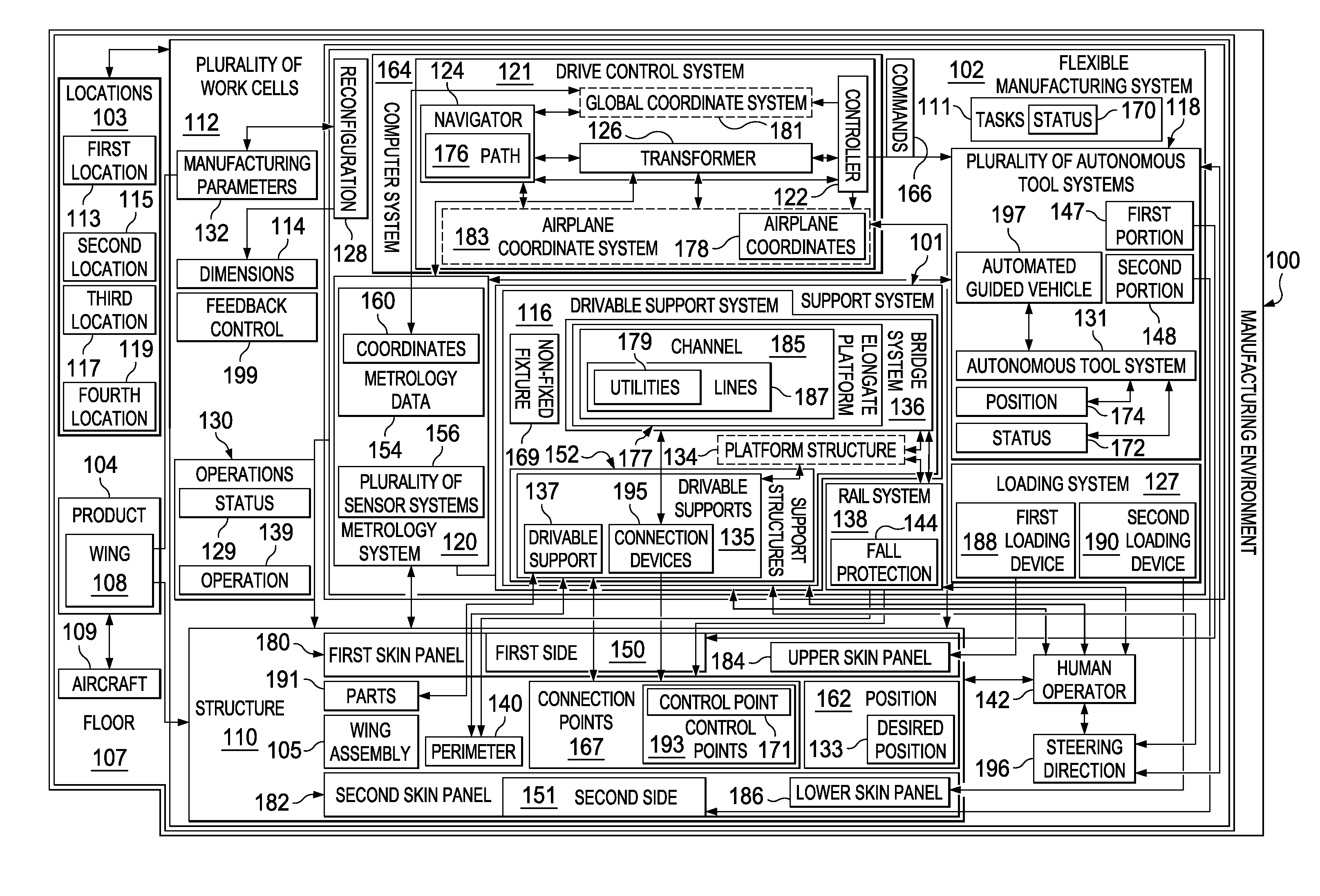
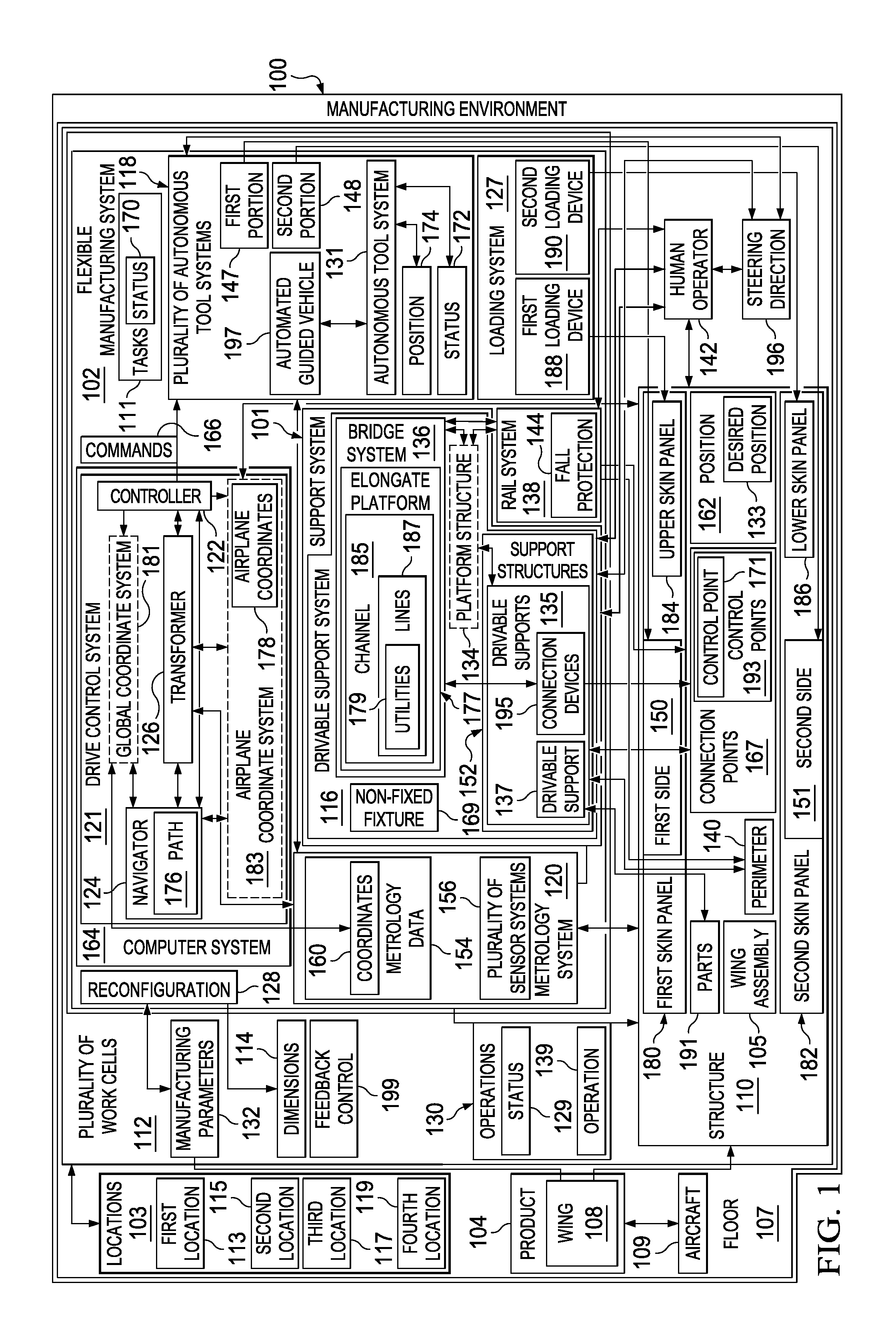
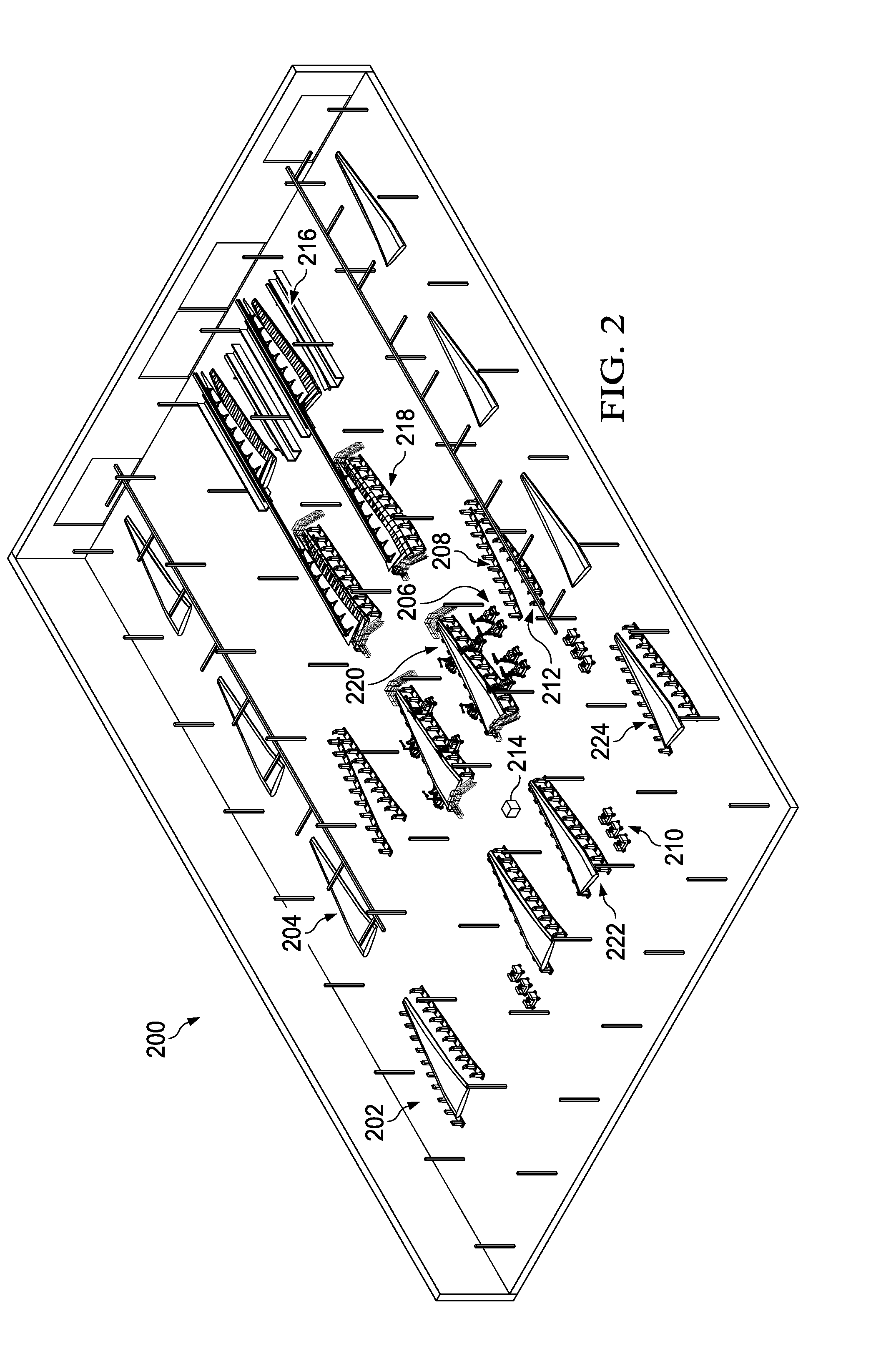
The patent describes a flexible manufacturing system for aircraft structures that uses autonomous tool systems and a drivable support system to hold the structure in place while it is being worked on. The system can be moved across the floor of the manufacturing environment to perform operations on the structure. The system also includes a metrology system to help with positioning the structure and the tooling used in the manufacturing process. The technical effects of this system include improved efficiency and accuracy in the manufacturing process, as well as reduced labor and materials costs.

Problems solved by technology

Manufacturing aircraft structures may be a complex and time-consuming process.
Countless labor hours are needed for human operators to assemble and inspect the aircraft structure.
The movement and repositioning of the aircraft structure may cause undesired delays in the manufacturing process, which increase the production time for the aircraft structure.
In addition, the process of using fixed monument fixtures may take up more room than desired in the manufacturing facility, allow limited access to the aircraft structure for human operators, or both.
The need for human operators to transport parts to fixed monument fixtures and maneuver within and around these fixed monument fixtures also may increase the time, complexity, and cost of assembling the aircraft more than desired.
Additionally, fixed monument fixtures may be difficult to modify or move since fixed monument fixtures are heavy, secured to the floor, or both.

Method used


Image

  • Flexible Manufacturing System for Aircraft Structures
  • Flexible Manufacturing System for Aircraft Structures
  • Flexible Manufacturing System for Aircraft Structures

Examples


Embodiment Construction

[0057]The illustrative embodiments recognize and take into account one or more different considerations. For example, without limitation, the illustrative embodiments recognize and take into account that it may be desirable to assemble an aircraft structure without the use of fixed monument fixtures at different locations within the manufacturing facility. These fixed monument fixtures may be large, bulky, structures that take up significant amounts of space in the manufacturing facility. As a result, the number of work cells available in the manufacturing facility may be limited, which reduces the number of aircraft structures that may be assembled at the same time.

[0058]Additionally, the illustrative embodiments recognize and take into account that when maintenance or rework needs to be performed on the fixed monument fixtures, production of aircraft structures may be slowed until the fixed monument fixture is repaired. Fixed monument fixtures are not easily replaceable without si...


PUM

PropertyMeasurementUnit
flexibleaaaaaaaaaa
heightaaaaaaaaaa
current positionaaaaaaaaaa

Abstract

A method and apparatus for manufacturing an aircraft structure. A drivable support may be driven from a first location to a second location to bring the drivable support together with at least one other drivable support to form a drivable support system. A structure may be held in a desired position using the drivable support system.

Description

RELATED PROVISIONAL APPLICATION[0001]This application claims the benefit of U.S. Provisional Patent Application Ser. No. 61 / 986,824, filed Apr. 30, 2014, and entitled “Flexible Manufacturing System for Aircraft Structures.”CROSS-REFERENCE TO RELATED APPLICATIONS[0002]This application is related to the following patent applications: entitled “Crawler Robot and Supporting Platform,” Ser. No. ______, attorney docket no. 12-1639-US-NP; entitled “System and Method for Positioning an Automated Assembly Tool Relative to a Structure,” Ser. No. ______, attorney docket no. 14-0419-US-NP; entitled “Metrology System for Positioning Assemblies,” Ser. No. ______, attorney docket no. 12-1521-US-NP; entitled “Mobile Automated Assembly Tool for Aircraft Structures,” Ser. No. ______, attorney docket no. 14-0429-US-NP; entitled “Mobile Automated Overhead Assembly Tool for Aircraft Structures,” serial no.______, attorney docket no. 14-0481-US-NP; and entitled “Apparatus, System, and Method for Supporti...

Claims


Application Information

Patent Timeline
Patent Type & Authority Applications(United States)
IPC IPC(8): B64F5/00B23P21/00B23B41/00
CPCB64F5/0009B23B41/00B23P21/004Y10T408/52Y10T29/50Y10T408/03B23B2215/04B64F5/10
Inventor DAY, DAN DRESSKELLMUNK, CLAYTON LYNNSCHMITT, STEVEN JOHNREID, ERIC M.
Owner THE BOEING CO
Learn More