Tool Protector

a tool protector and tool technology, applied in the field of hand tools, can solve the problems of bending and breaking, affecting the use of users, and extending from the distal end of the body defining the handle, so as to prevent bending and breaking

Inactive Publication Date: 2015-11-12
CARRERA JOSE
View PDF6 Cites 2 Cited by
  • Summary
  • Abstract
  • Description
  • Claims
  • Application Information

AI Technical Summary

Benefits of technology

[0014]The device herein disclosed and described provides a solution to the shortcomings in prior art. The device achieves the above noted goals through the provision of an easily engaged, and disengaged annular or cylindrical guard member. When disengaged from two connection points on the handle, the guard member is slidable between a first or projecting position surrounding the projecting tool at the distal end of the handle, to a second or retracted position, exposing the projecting tool. In the projecting position, the tool guard, provides 360 degrees of protection to protect the sharp or pointed tool projecting from on end of a handle from damage. Additionally, the cylindrical guard member also protects the user from harm from the business end of the sharp or pointed tool when carrying such on their person. The handle and cover may be formed of polymeric material, carbon fiber, plastic, metal, or other materials suitable to the task. In the case of the cover is should be formed sufficiently strong to resist impacts when in the projected position to prevent bending and breaking.

Problems solved by technology

Machinists, craftsman, and other professionals employ a wide range of customized, expensive, and somewhat easily damaged tools.
In either case, the tool when not being employed, and projecting from the distal end of the body defining the handle, is easily damaged by impacts, being drop, or being otherwise mishandled.
Further, many such tools can be sharp or injurious to the user should they inadvertently come into contact with the business end of the tool itself.
This leaves long gaps between the projecting flexible members which expose the tool to contact and damage, and expose the user to potential harms from the tool which frequently is very sharp or pointed or both.
Further, the projecting members being flexible, should a large amount of force be encountered from a side direction, they easily bend.
Further, the bending of the members can allow the sharp or pointed tool to project from the gaps between the members and harm the user.
Considering the user may carry multiple such tools at a time in a belt, or pocket, or on their person, the potential for damage to the tool, and injury to the person multiples with each such tool carried and stored.
In addition, employment of the protector in conventional tool protections is cumbersome at best.
Trying to bend or otherwise deflect the engagement end of the flexible members, while working, to move them into a stored position or retracted position, is at best an irritant to the user.
Various limitations of the related art will become apparent to those skilled in the art upon a reading and understanding of the specification below and the accompanying drawings.

Method used


Image

  • Tool Protector
  • Tool Protector
  • Tool Protector

Examples


Embodiment Construction

[0032]In this description, the directional prepositions of up, upwardly, down, downwardly, front, back, top, upper, bottom, lower, left, right and other such terms refer to the device as it is oriented and appears in the drawings and are used for convenience only; they are not intended to be limiting or to imply that the device has to be used or positioned in any particular orientation.

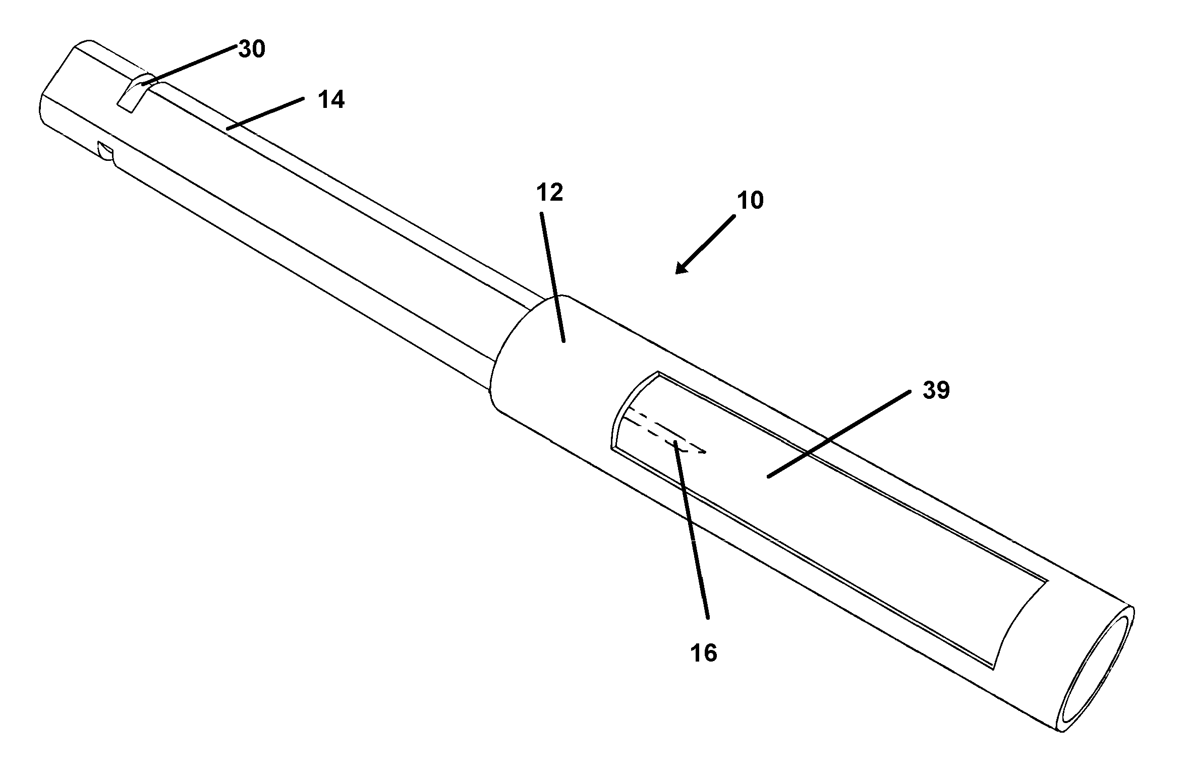
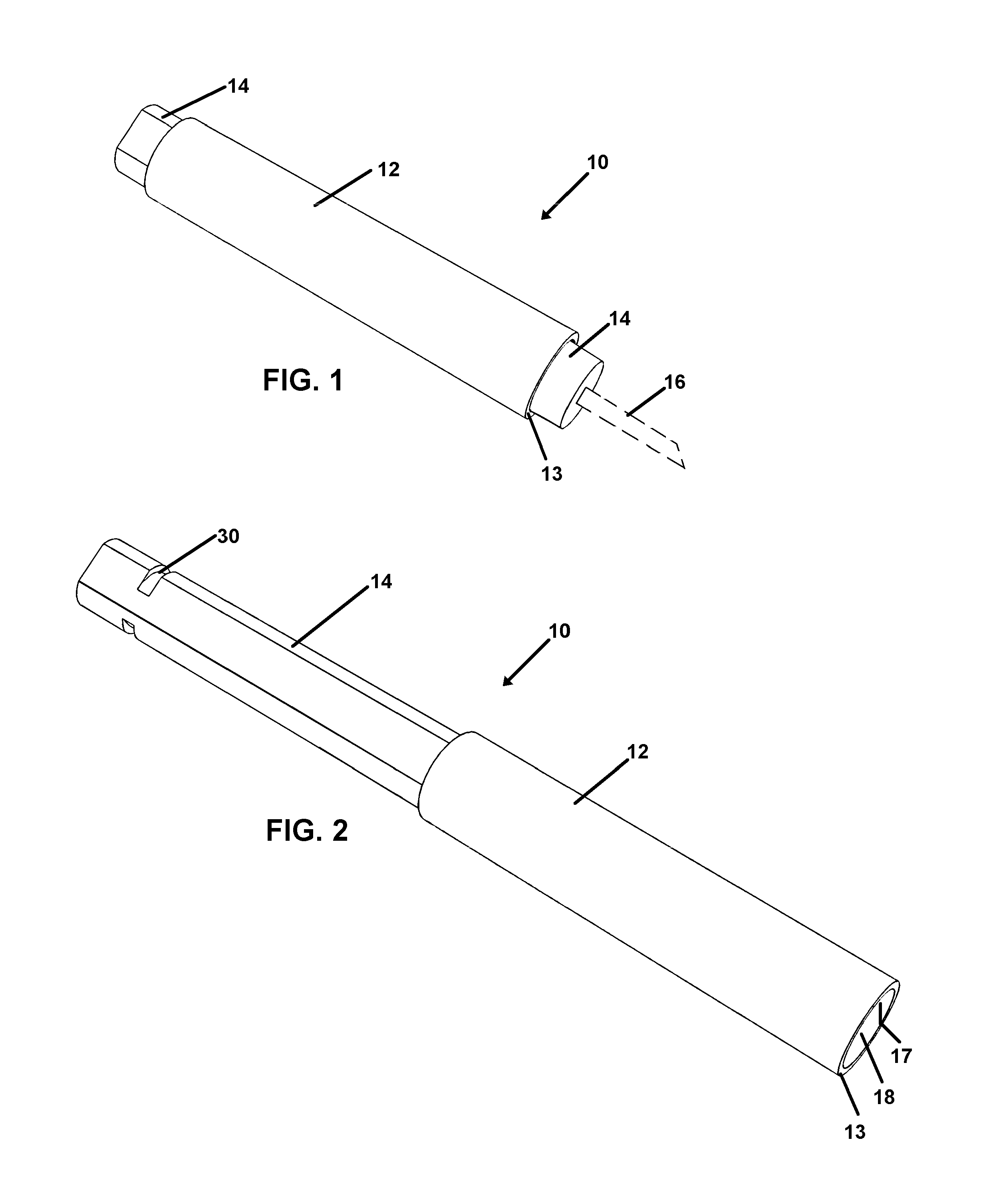
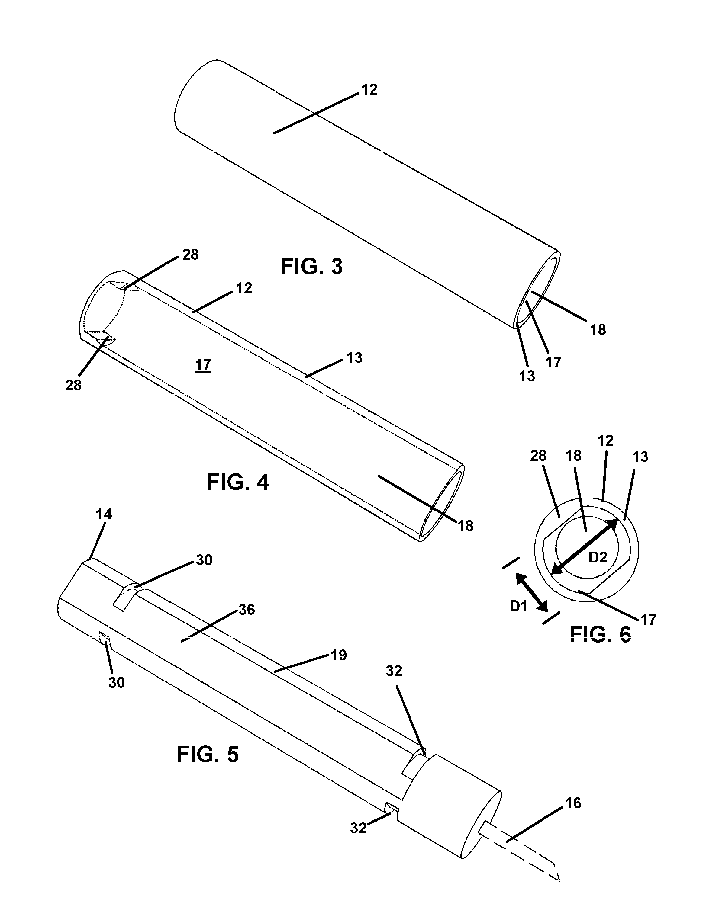
[0033]Now referring to drawings in FIGS. 1-7 there is seen in FIG. 1 the device 10 herein with a translatable cover 12 formed by a cylindrical wall 13 having an interior wall surface 17 defining a diameter of an axial cavity 18 sized in diameter to translate on the exterior surface of the body defining a handle 14. The handle has a first end opposite a distal end which is engaged with a tool 16 projecting substantially axially therefrom, which herein is depicted as a generic mode of the tool 16 since the shape and configuration of such tools is virtually limitless as they are all adapted to the task i...


PUM


Abstract

A tool protector system for a tool projecting from a distal end of a handle is provided having a cover with a sidewall which surrounds the tool projecting from the handle when in a projecting position. The cover is translatable to a retracted position on the handle exposing the tool and distal end of the handle when the tool is to be employed. A twisting of the cover relative to the handle allows for removably engaging the cover to the handle to hold the cover either in the projecting position or retracted position. The system works especially well with tools employed for manipulating electric contacts engaged with wiring to protect the user from the business end of the tool and the tool from damage when not in use.

Description

[0001]This application claims priority to U.S. Provisional Patent Application Ser. No. 61 / 991,364 filed on May 9, 2014 and which is incorporated herein in its entirety by this reference thereto.BACKGROUND OF THE INVENTION[0002]1. Field of the Invention[0003]The present invention relates to hand tools used to manipulate electrical contacts during their insertion or removal into or from rear release electrical connectors. More particularly, the disclosed device relates to a device and method providing protective covering to protect both the tool engaged to the handle and the user from the tool itself.[0004]2. Prior Art[0005]Machinists, craftsman, and other professionals employ a wide range of customized, expensive, and somewhat easily damaged tools. Such tools are portable and typically comprise an elongated handle having an engaged or engageable specific tool projecting from a body defining the handle at one end of the handle. Typically the tool itself is customized to the job to be ...

Claims


Application Information

Patent Timeline
Patent Type & Authority Applications(United States)
IPC IPC(8): B25G1/08B25G1/04
CPCB25G1/04B25G1/08B25G1/12
Inventor CARRERA, JOSE
Owner CARRERA JOSE
Why Eureka
Try Eureka