Aircraft landing gear equipped with means for driving in rotation wheels carried by the landing gear

a technology for landing gear and rotating wheels, which is applied in the direction of vehicle components, wheel arrangements, energy-saving operational measures, etc., can solve the problems of difficulty in coupling wheel rims to ring gears, and achieve the effect of cost-effective and easy production

Active Publication Date: 2015-11-12
SAFRAN LANDING SYSTEMS
View PDF20 Cites 8 Cited by
  • Summary
  • Abstract
  • Description
  • Claims
  • Application Information

AI Technical Summary

Benefits of technology

[0004]The object of the invention is to reduce the cost and the mass of means for driving in rotation an aircraft wheel and to make these drive means more tolerant of a deformation of the rim of the wheel.SUMMARY OF THE INVENTION
[0006]The first blocks constitute a ring gear engaged by the gearwheel of the drive actuator, said ring gear being easy to produce, cost-effective and relatively lightweight since it is formed solely of first blocks and means for fixing said blocks to the rim. When the rim is deformed, the first blocks move, but are not distanced from the gearwheel of the actuator, which follows the displacement of the first blocks. The first blocks thus may still cooperate with the gearwheel of the actuator, such that the proposed drive is very tolerant of deformations.

Problems solved by technology

In addition to the problems posed by mass and cost, the designers and integrators of drive actuators are faced with a certain number of technical difficulties, in particular that of the deformation under load of the rim of the wheel, which makes it difficult to couple said wheel rim to a ring gear driven by the pinion of a drive actuator.

Method used


Image

  • Aircraft landing gear equipped with means for driving in rotation wheels carried by the landing gear
  • Aircraft landing gear equipped with means for driving in rotation wheels carried by the landing gear
  • Aircraft landing gear equipped with means for driving in rotation wheels carried by the landing gear

Examples


first embodiment

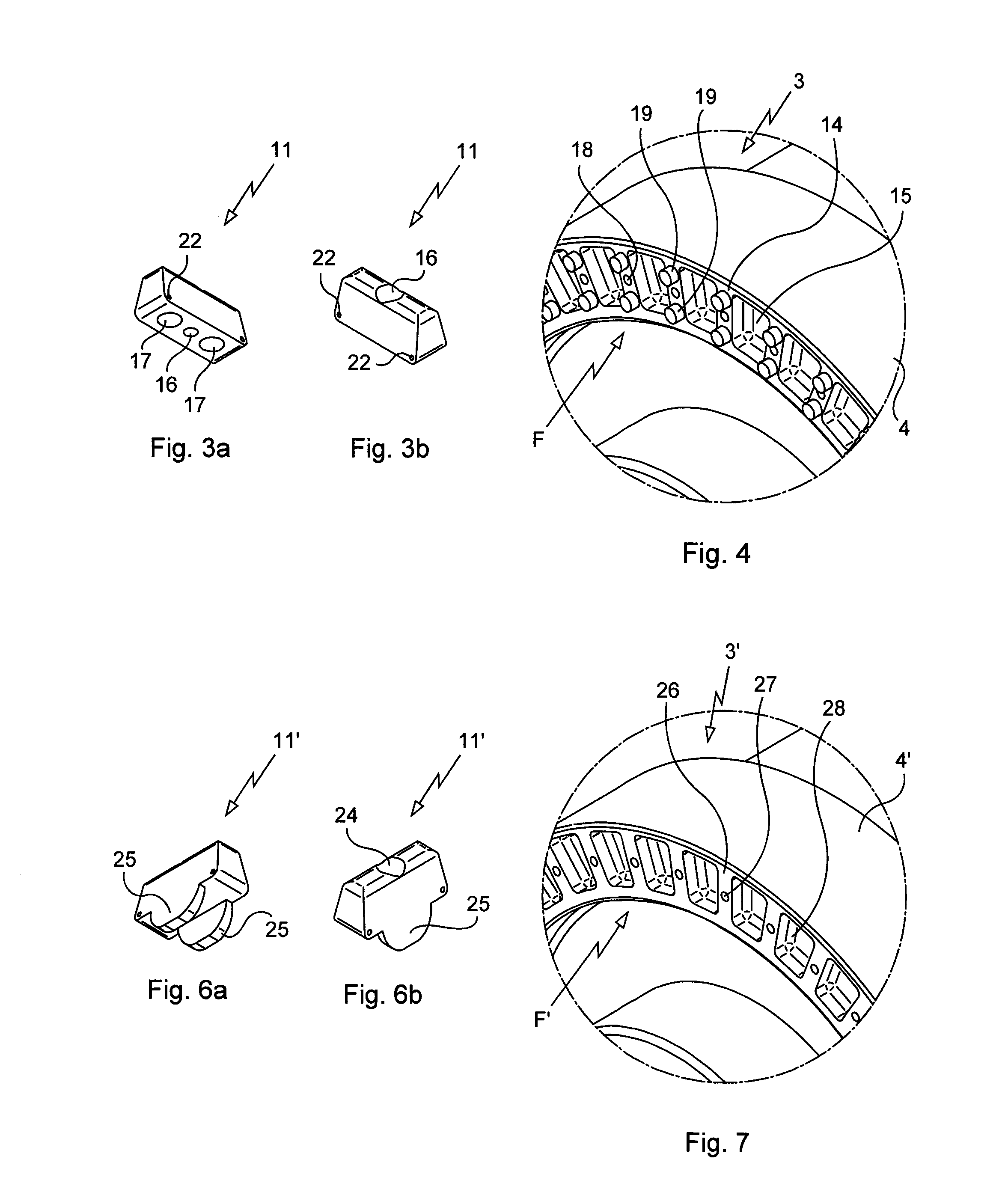
[0028]In the invention visible in FIGS. 3a, 3b and 4, the lateral face F of the rim 4 of the wheel 3 is shaped so as to receive the first blocks 11. The lateral face F has radial supports 14 separated by indentations 15 and arranged over the circumference of the lateral face F. The first blocks 11 are carried on the radial supports 14. Each first block 11 comprises a smooth bored hole 16 passing through the first block 11 from one side to the other, and also two positioning holes 17. When the first block 11 is mounted on the corresponding radial support 14, the smooth bored hole 16 is lengthened by a tapped hole 18 arranged on the radial support 14, and the two positioning holes 17 receive two complementary pins 19 also arranged on the radial support 14.

[0029]Thus, in order to fix each first block 11 on the lateral face F of the rim 4, the first block 11 is positioned on the radial support 14 by means of the positioning holes 17 and the complementary pins 19, then the first block 11...

second embodiment

[0032]FIGS. 5a, 5b and 6 show the invention with reference to a wheel 3′ comprising a rim 4′ having a lateral face F′. Each first block 11′ comprises a smooth bored hole 24 passing through the first block 11′ from one side to the other as well as two lateral positioning ears 25. When the first block 11′ is mounted on a corresponding radial support 26, the smooth bored hole 24 is lengthened by a threaded hole 27 arranged on the radial support 26, and the two ears 25 extend in indentations 28 arranged on either side of the corresponding radial support 26 of the lateral face F′ of the rim 4′.

[0033]Thus, in order to fix each first block 11′ on the lateral face F′ of the rim 4′, the first block 11′ is positioned on the radial support 26 by means of the ears 25, then said first block is fixed on the support 26 by means of a screw extending into the smooth bored hole 24 and into the threaded hole 27.

[0034]Advantageously, and with reference again to FIG. 2, the teeth 13 of the gearwheel 8 o...


PUM


Abstract

A landing gear that comprises an axle (2) and a wheel (3, 3′). The wheel comprises a rim (4, 4′) mounted so as to rotate on the axle about a first axis of rotation (X), first blocks protruding from a lateral face (F, F′) of the rim, the first blocks being adapted to cooperate with a gearwheel (8) of a drive actuator (7) carried by the landing gear. The gearwheel is mounted rotatably about a second axis of rotation (Y) perpendicular to the first axis of rotation.

Description

[0001]The invention relates to an aircraft landing gear equipped with means for driving in rotation wheels carried by the landing gear.BACKGROUND OF THE INVENTION[0002]Aircraft constructors are prompted for a number of reasons to attempt to motorize the wheels of aircraft, in particular by using drive actuators equipped with electric motors. Such a motorization in fact presents significant environmental and economical advantages (reduction of fuel consumption, reduction of noise during the taxiing phases, etc.) and makes it possible to provide new functions: piloting the aircraft on the ground remotely, manoeuvring the aircraft when the propulsion engines are switched off, taxiing in reverse, etc.[0003]In addition to the problems posed by mass and cost, the designers and integrators of drive actuators are faced with a certain number of technical difficulties, in particular that of the deformation under load of the rim of the wheel, which makes it difficult to couple said wheel rim t...

Claims


Application Information

Patent Timeline
Patent Type & Authority Applications(United States)
IPC IPC(8): B64C25/40B64C25/34
CPCB64C25/34B64C25/405Y02T50/80
Inventor MAZARGUIL, NICOLAS
Owner SAFRAN LANDING SYSTEMS
Why Eureka
Try Eureka