Expandable Bolt With Thrust Element

a technology of thrust element and expandable bolt, which is applied in the field of expandable bolt with thrust element, can solve the problem of reducing the effective length of the bor

Inactive Publication Date: 2015-11-12
FCI HLDG DELAWARE
View PDF5 Cites 0 Cited by
  • Summary
  • Abstract
  • Description
  • Claims
  • Application Information

AI Technical Summary

Benefits of technology

[0006]The present invention includes a rock bolt having a longitudinally expandable tube. The tube includes a longitudinally extending depression that defines a temporary, enclosed longitudinal passageway. A thrust element is positi

Problems solved by technology

Compaction of loose material in the bore is problematic as it reduces the effective length of the bore and

Method used


Image

  • Expandable Bolt With Thrust Element
  • Expandable Bolt With Thrust Element
  • Expandable Bolt With Thrust Element

Examples


Embodiment Construction

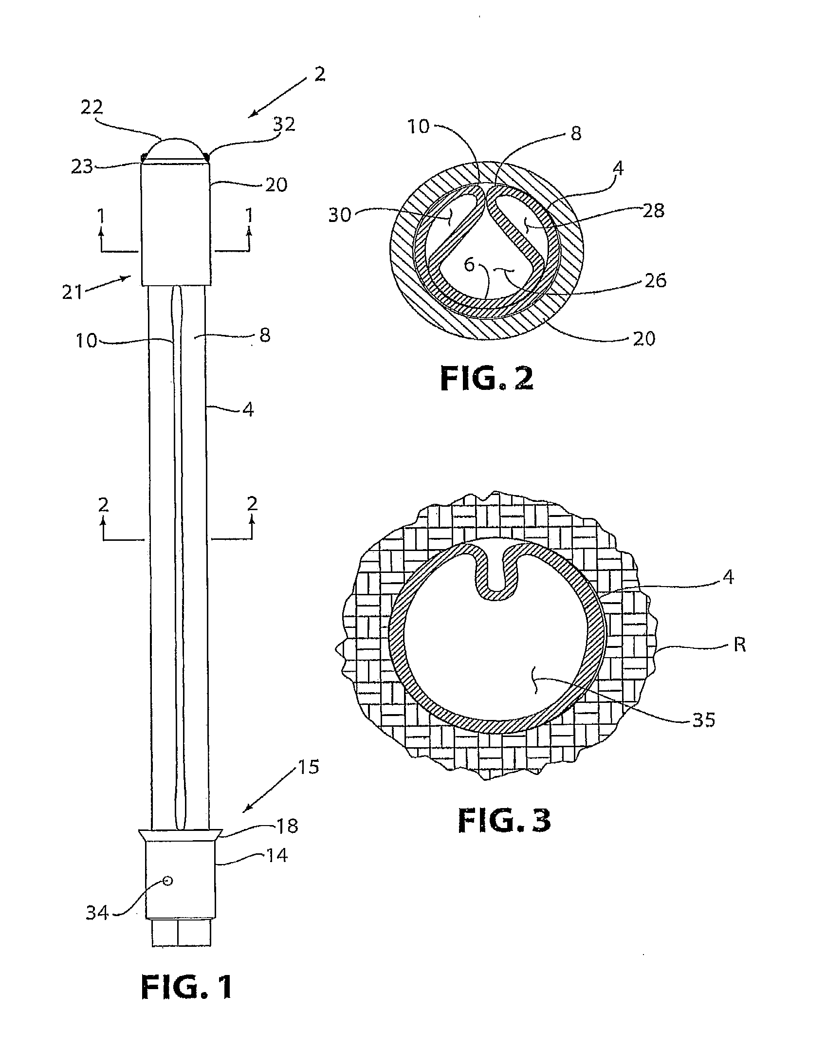
[0035]Referring now to the drawing figures in which like reference numbers refer to like elements, FIG. 1 shows a rock bolt 2 which includes an expandable tube 4 having an initial cross-sectional profile as shown in FIG. 2. The tube 4 is partially collapsed upon itself (such as by rolling or drawing) so as to provide a depressed region 6 between two curved outer portions 8, 10 extending longitudinally along the tube 4. The tube 4 is produced from a steel alloy or the like having sufficient strength to function in rock support, even after deformation from internal hydraulic pressure as described below. A first stiffening tube 14, having a sidewall and two open ends, is attached to and surrounds a proximal end 15 of the tube 4. A lip 18 may extend from stiffening tube 14 for engaging with a rock surface when the rock bolt 2 is inserted in the borehole.

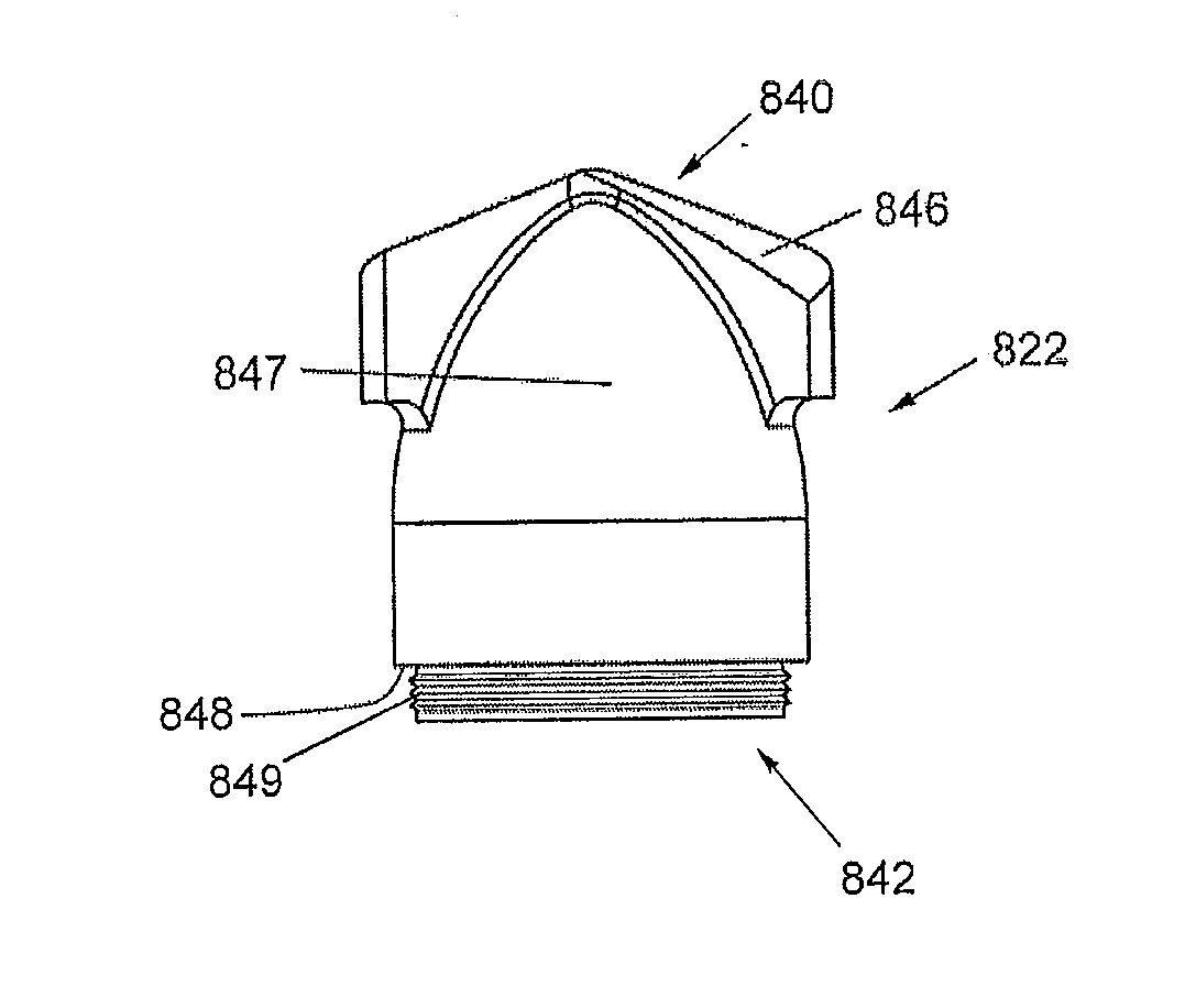
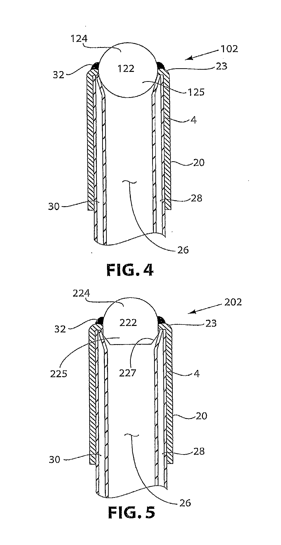
[0036]A second stiffening tube 20, having a sidewall and two open ends, is attached to and surrounds a distal end 21 of tube 4 leaving ...


PUM


Abstract

The present invention includes a rock bolt having a longitudinally expandable tube. The tube includes a longitudinally extending depression that defines a temporary enclosed longitudinal passageway. The rock bolt further includes a shielded distal end to prevent debris from entering the temporary enclosed longitudinal passageway. The distal end includes a thrust element that facilitates movement of loose material across the rock bolt as it is advanced in a borehole. The present invention also includes a method of making such a rock bolt and a method of using such a rock bolt.

Description

BACKGROUND OF THE INVENTION[0001]1. Field of the Invention[0002]This invention relates to a rock bolt having an expandable tube and a shielded distal end bearing a thrust element, a method of making such a rock bolt, and a method of using such a rock bolt.[0003]2. Description of Related Art[0004]Rock bolts are used in underground mines, such as coal mines, to support the roof and ribs. Installation of conventional rock bolts involves drilling a borehole into the rock to a desired depth using an elongated drilling tool (termed the “drill steel”), removing the drill steel from the borehole, optionally inserting adhesive resin cartridges, and retaining the cartridges in the blind end of the borehole while a bolt, optionally bearing an expansion anchor, is installed into the borehole. The free end of the bolt extending out of the borehole is received by a chuck of a bolting machine. The bolting machine rotates the bolt within the borehole to mix the adhesive resin and / or expand the expa...

Claims


Application Information

Patent Timeline
IPC IPC(8): E21D21/00E02D5/80E21D20/00
CPCE21D21/0033E21D20/00E02D5/805E21D21/0093E21D21/008E21D21/0073
Inventor MARTIN, DAVID A.ARNOT, JEREMY ROSS
Owner FCI HLDG DELAWARE
Why Eureka
Try Eureka