High Tension Valve Spring and Valve Float Eliminator

a valve spring and high-pressure technology, applied in the direction of valve details, non-mechanical valves, valve arrangements, etc., can solve the problems of poor power transmission, catastrophic failure, and poor fuel consumption ra

Inactive Publication Date: 2015-11-12
BARBER MICHAEL
View PDF2 Cites 0 Cited by
  • Summary
  • Abstract
  • Description
  • Claims
  • Application Information

AI Technical Summary

Benefits of technology

This patent describes an innovation in how cylinders in internal combustion engines are opened and closed by their valves. Traditionally, these valves were controlled by springs which caused them to close when they reached their maximum movement point (called top dead center). However, this new technology uses other methods like gases or liquids that flow through pipes to make sure all the valves move at exactly the same time. By doing this, it becomes easier to control the timing between different parts of the engine's operation.

Problems solved by technology

The technical problem addressed in this patent is how to achieve reliable and efficient valve actuation without the need for expensive and complicated designs like desmodromics.

Method used


Image

  • High Tension Valve Spring and Valve Float Eliminator
  • High Tension Valve Spring and Valve Float Eliminator
  • High Tension Valve Spring and Valve Float Eliminator

Examples


Embodiment Construction

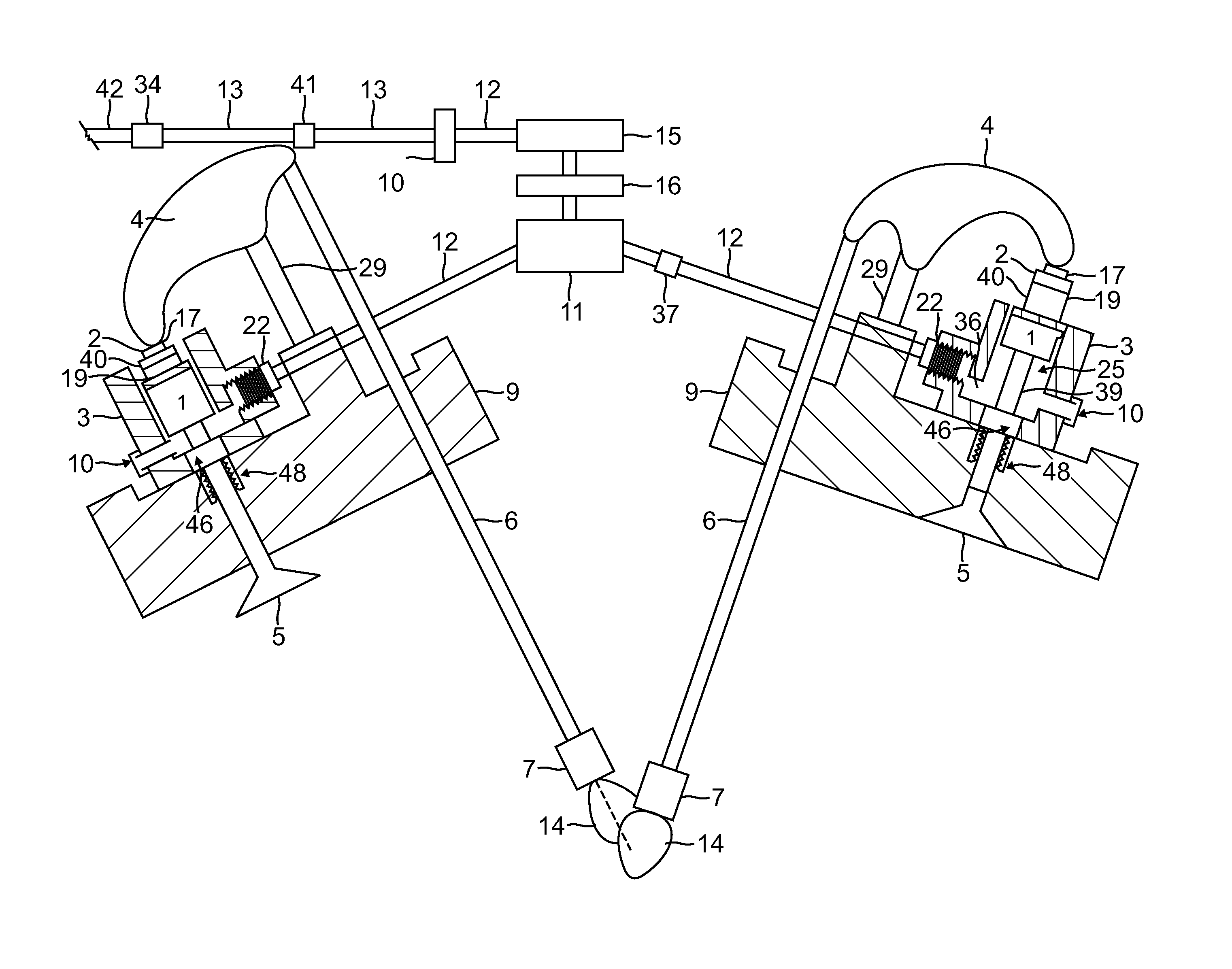
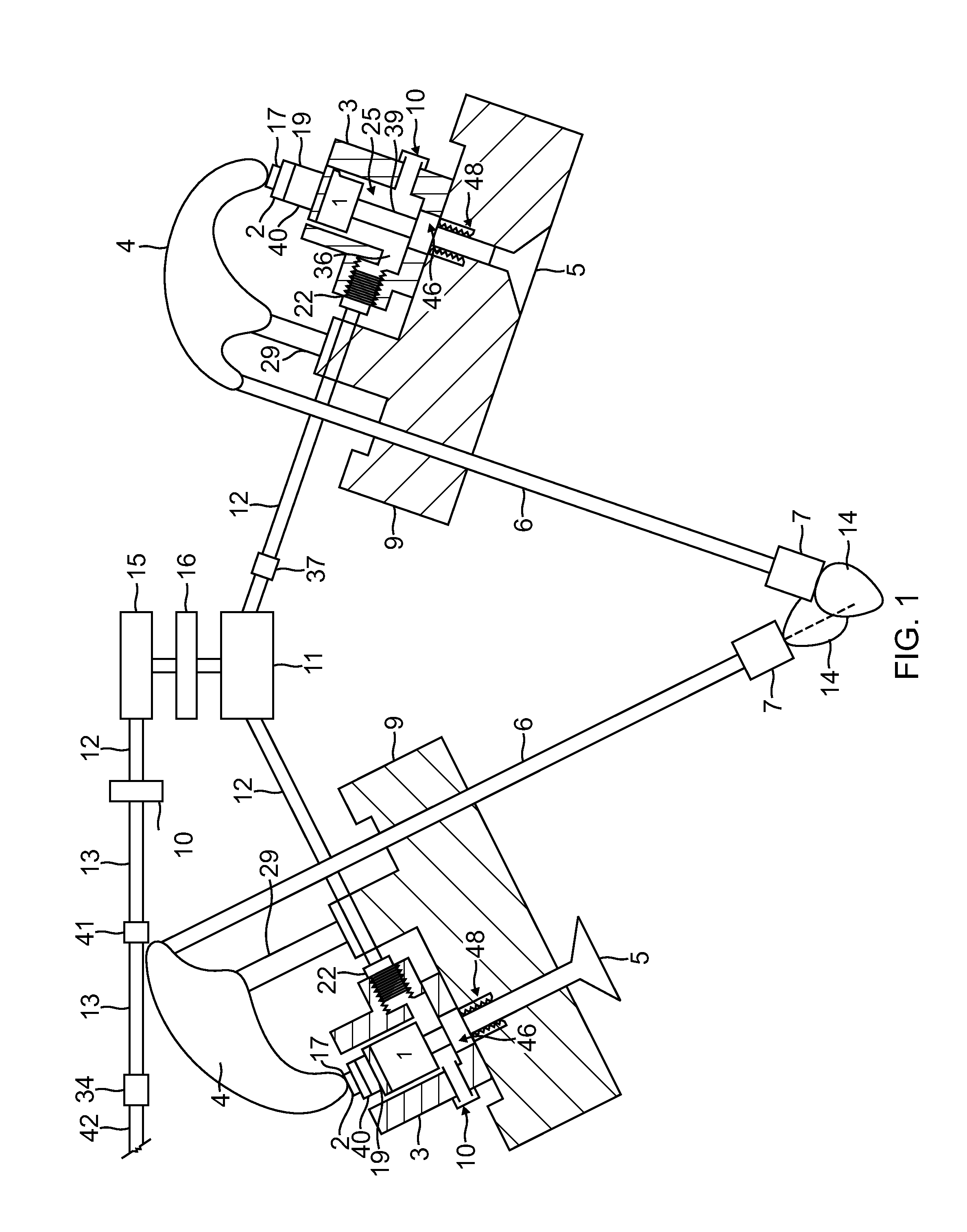
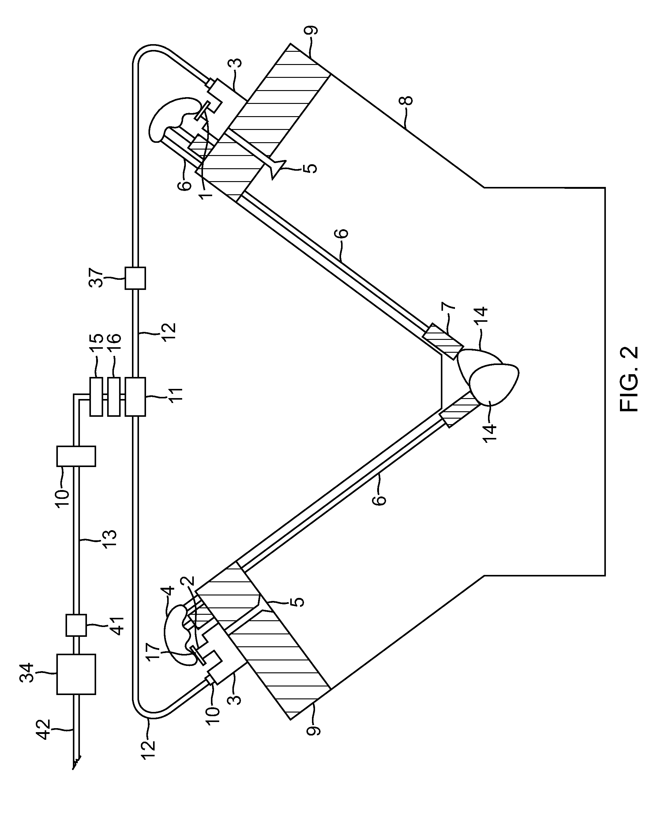
[0088]Most multiple cylinder engines have for every cylinder an exact opposite cylinder firing in perfect synchronization. This invention utilizes this opposite firing principle, when a cylinder is ready to fire and the valves are closed and ready for combustion, the exact opposite is occurring in a different cylinder. We can use this phenomena to cause action in its opposite firing cylinder with perfect synchronization of movement. This invention is a standalone valve actuation system with backup components which can be used for practically any multiple cylinder engine. There is no pump needed as each opposite cylinders existing rocker arm powers the actuator cylinder which power each other. This invention utilizes the engines original camshaft, lifters rocker arms and pushrods and is installed on top of the engine and requires little or no machining to retrofit the existing engine.

[0089]The present invention takes an enormous amount of stress from the engines valve train as one ty...


PUM


Abstract

An internal combustion engine cylinder valve actuation system permitting elimination of valve springs. Valve opening and closing is actuated by a valve actuation means such as pressurized liquid or gas, or else mechanical wires or linkage means. The energy created by combustion causes liquid or gas valve actuation means to oscillate or else circulate between corresponding cylinder valves causing synchronized valve opening and closing between those cylinders. Mechanical linkages similarly comprise physical connections between corresponding cylinder valves and effect synchronized valve opening and closing between those cylinders. The above system thereby eliminates valve float and valve spring failure where valve springs are not required and a typical internal combustion engine is easily retrofitted to accommodate this system.

Description


Claims


Application Information

Patent Timeline
Owner BARBER MICHAEL
Why Eureka
Try Eureka