Compact PIFA Antenna

a pifa antenna and compact technology, applied in the field of compact planar invertedf antennas, can solve the problems of complicated antenna selection and integration process, and achieve the effect of reducing the area of the ground, reducing the area of the antenna, and suitable impedance bandwidth

Active Publication Date: 2015-11-12
ENERGOUS CORPORATION
View PDF2 Cites 57 Cited by
  • Summary
  • Abstract
  • Description
  • Claims
  • Application Information

AI Technical Summary

Benefits of technology

[0007]Various embodiments of PIFAs described herein may include an antenna element with two or more slots formed over the top layer of a printed circuit board (PCB), where these antenna slots may be designed for reducing the area of the antenna while keeping a suitable impedance bandwidth. These PIFA configurations may also include a ground element formed on the bottom layer of the PCB and operatively coupled with the antenna element through ground and signal vias. The ground element may also include one or more slots design...

Problems solved by technology

This is becoming more relevant as the trend of smaller hand held electronic devices with an increasi...

Method used


Image

  • Compact PIFA Antenna
  • Compact PIFA Antenna
  • Compact PIFA Antenna

Examples


Embodiment Construction

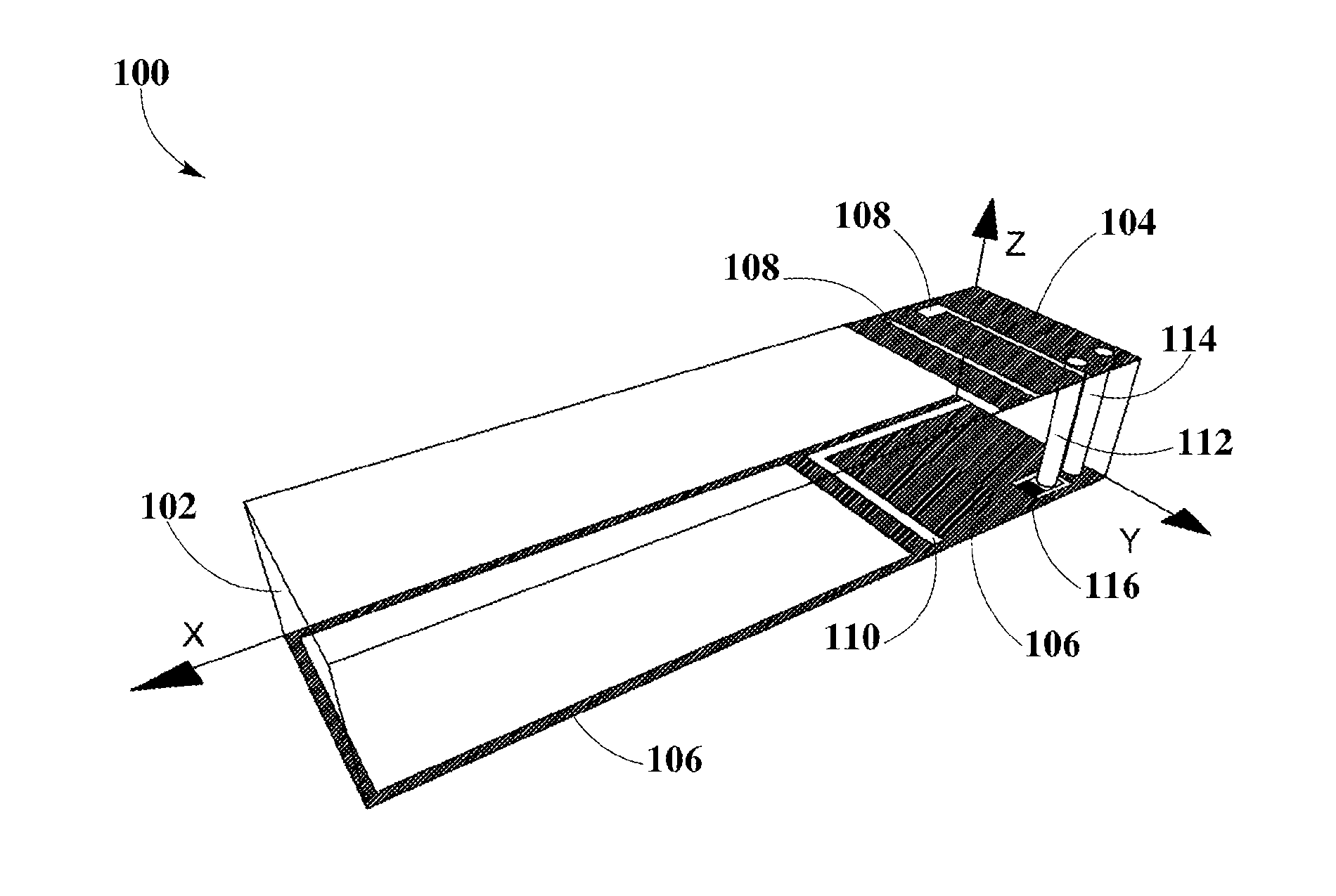
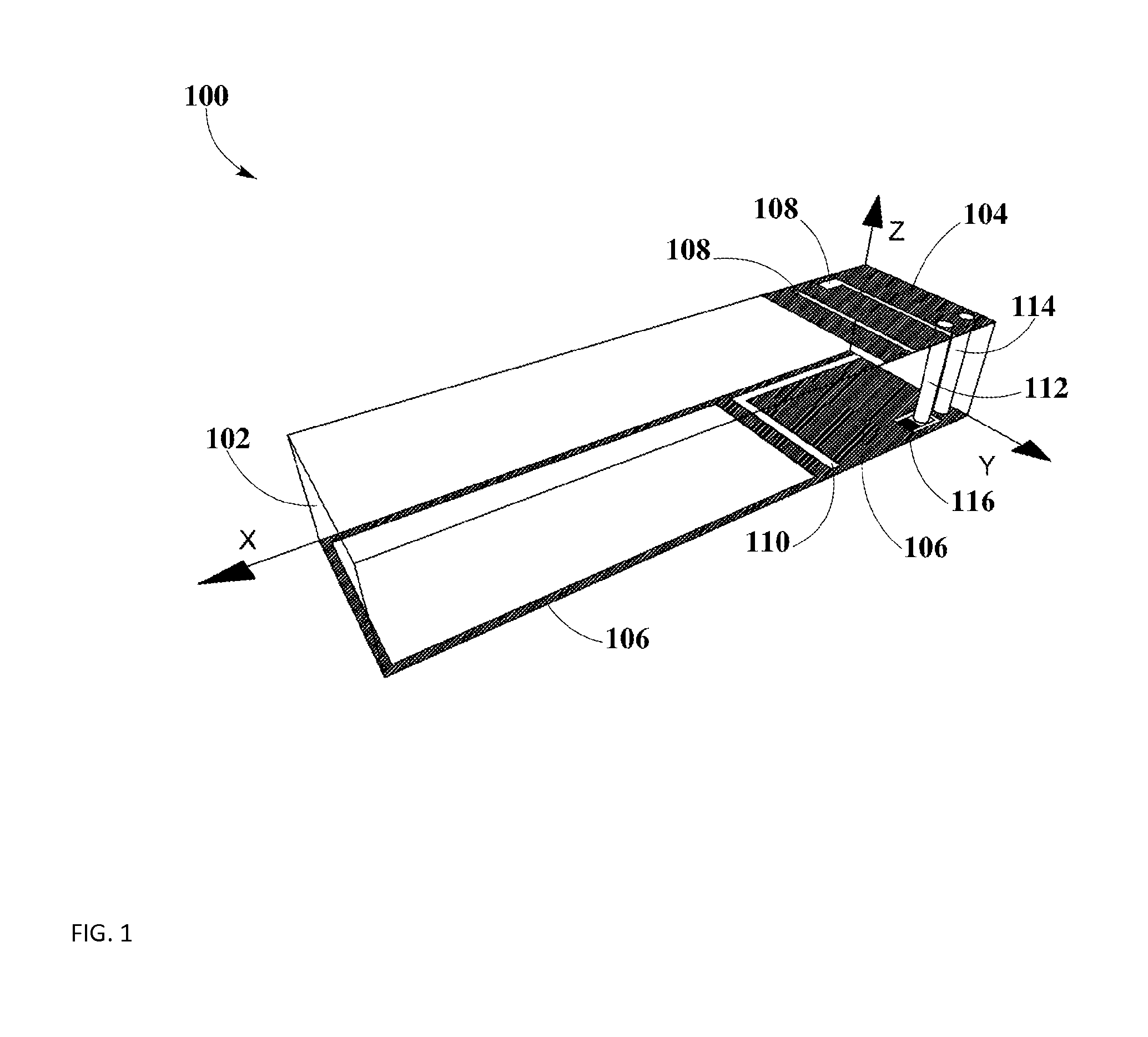
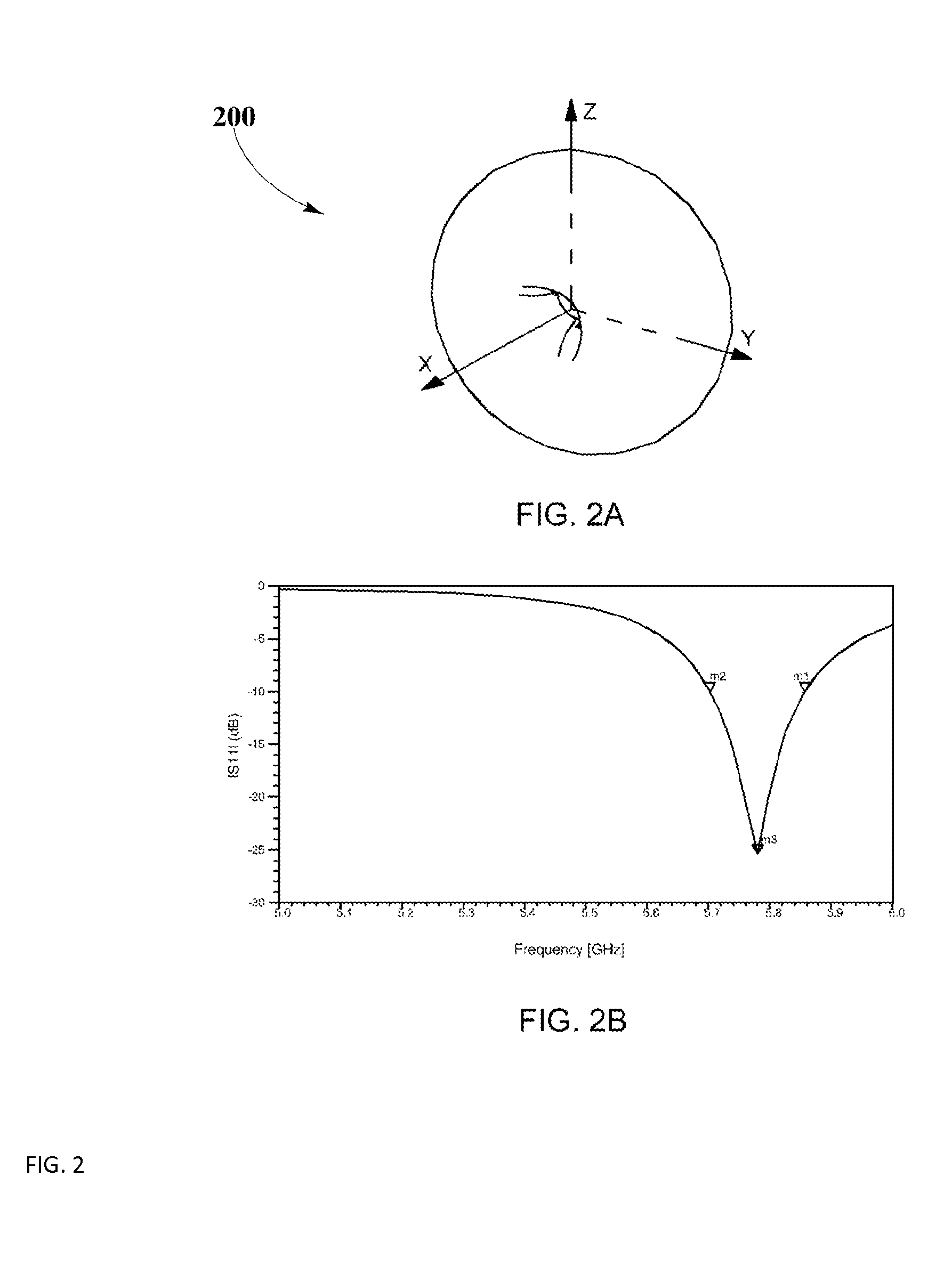
[0024]The present disclosure is here described in detail with reference to embodiments illustrated in the drawings, which form a part here. Other embodiments may be used and / or other changes may be made without departing from the spirit or scope of the present disclosure. The illustrative embodiments described in the detailed description are not meant to be limiting of the subject matter presented here.

DEFINITIONS

[0025]As used here, the following terms may have the following definitions:

[0026]“Wireless Power Transmission” may refer to the action of a transmitter capable of pocket forming for generating pockets of energy that may be utilized by a receiver for charging or powering an electronic device.

[0027]“Pocket-forming” may refer to generating two or more RF waves which converge in 3-d space, forming controlled constructive and destructive interference patterns.

[0028]“Pockets of energy” may refer to areas or regions of space where energy or power may accumulate in the form of cons...


PUM


Abstract

Various planar inverted-F antenna configurations may include an antenna element formed on the top of a PCB and a ground element formed on the bottom of the PCB. Two or more slots may be included in the antenna element for reducing the antenna area while maintaining a suitable impedance bandwidth. A slot may be included in the ground element for reducing the ground area while increasing radiation efficiency. A folded ground may be formed on the top of the PCB for reducing system area while maintaining suitable performance. By moving the folded ground closer to the antenna element and increasing the PCB thickness, significant reductions in system area may be achieved, while maintaining or improving performance in terms of radiation pattern, radiation efficiency and impedance bandwidth.

Description

CROSS-REFERENCE TO RELATED APPLICATIONS[0001]The present disclosure is related to U.S. non-provisional patent application DWV-3DPF-010 entitled “Methodology for Pocket-forming”; DWV-3DPF-027 entitled “Receivers for Wireless Power Transmission”; DWV-3DPF-029 entitled “Transmitters for Wireless Power Transmission,” which are each invented by Michael Leabman, and the entirety of which are incorporated herein by reference.BACKGROUND[0002]1. Field of the Disclosure[0003]The present disclosure relates in general to antennas, and more specifically, to compact planar inverted-F antennas (PIFAs) that can be integrated into receivers for wireless power transmission.[0004]2. Background Information[0005]Wireless power transmission may include a transmitter for forming and directing RF waves towards a receiver which may convert RF waves or pockets of energy into usable power for charging or powering an electronic device. The receiver may be integrated into the electronic device (i.e. a smartphon...

Claims


Application Information

Patent Timeline
IPC IPC(8): H02J17/00H01Q9/04H01Q1/48
CPCH02J17/00H01Q9/0407H01Q1/48H01Q9/0421H01Q5/364H02J50/27H02J50/005
Inventor CONTOPANAGOS, HARRYLEABMAN, MICHAEL
Owner ENERGOUS CORPORATION
Why Eureka
Try Eureka