Antenna for vehicle

Inactive Publication Date: 2006-08-10
CENT GLASS CO LTD
View PDF3 Cites 9 Cited by
  • Summary
  • Abstract
  • Description
  • Claims
  • Application Information

AI Technical Summary

Benefits of technology

[0036] According to the invention, the antenna can make it difficult for the antenna performance thereof to be affected by antenna setting locations or human bodies, and hence the actual antenna area can be reduced.
[0037] In addition, the antenna can increase the antenna performance higher than that provided by the conventional techniques and is hence preferable as a car telephone and portable telephone antenna, as well as a digital broadcast waves and TV broadcast waves reception antenna and furthermore can transmit and receive radio waves of personal radio communication equipment, commercial radio communication equipment and PHS.
[0038] Furthermore, the antenna can be provided which is difficult to be affected by the position on

Problems solved by technology

Conventionally, while rod antennas have been widely used as antennas for transmitting and receiving radio waves of car telephones and portable telephones and receiving television broadcast waves, since the construction of these rod antennas requires them to protrude from the vehicle body, there have been caused drawbacks that the protrusion of the antennas is not preferable from safety and aesthetic appearance aspects and that the protruding antenna constitutes a disturbance and may be broken when washing a vehicle.
However, since the antenna performance of any of the car telephone or portable telephone glass antennas shown in Patent Document No 1 to Patent Document No. 3 and the TV broadcast waves reception glass antennas shown in Patent Document No. 4 to Patent document No. 6 is liable to be affected by locations where the antenna is placed or structures in the vicinity of the antenna so placed,

Method used


Image

  • Antenna for vehicle
  • Antenna for vehicle
  • Antenna for vehicle

Examples


example 1

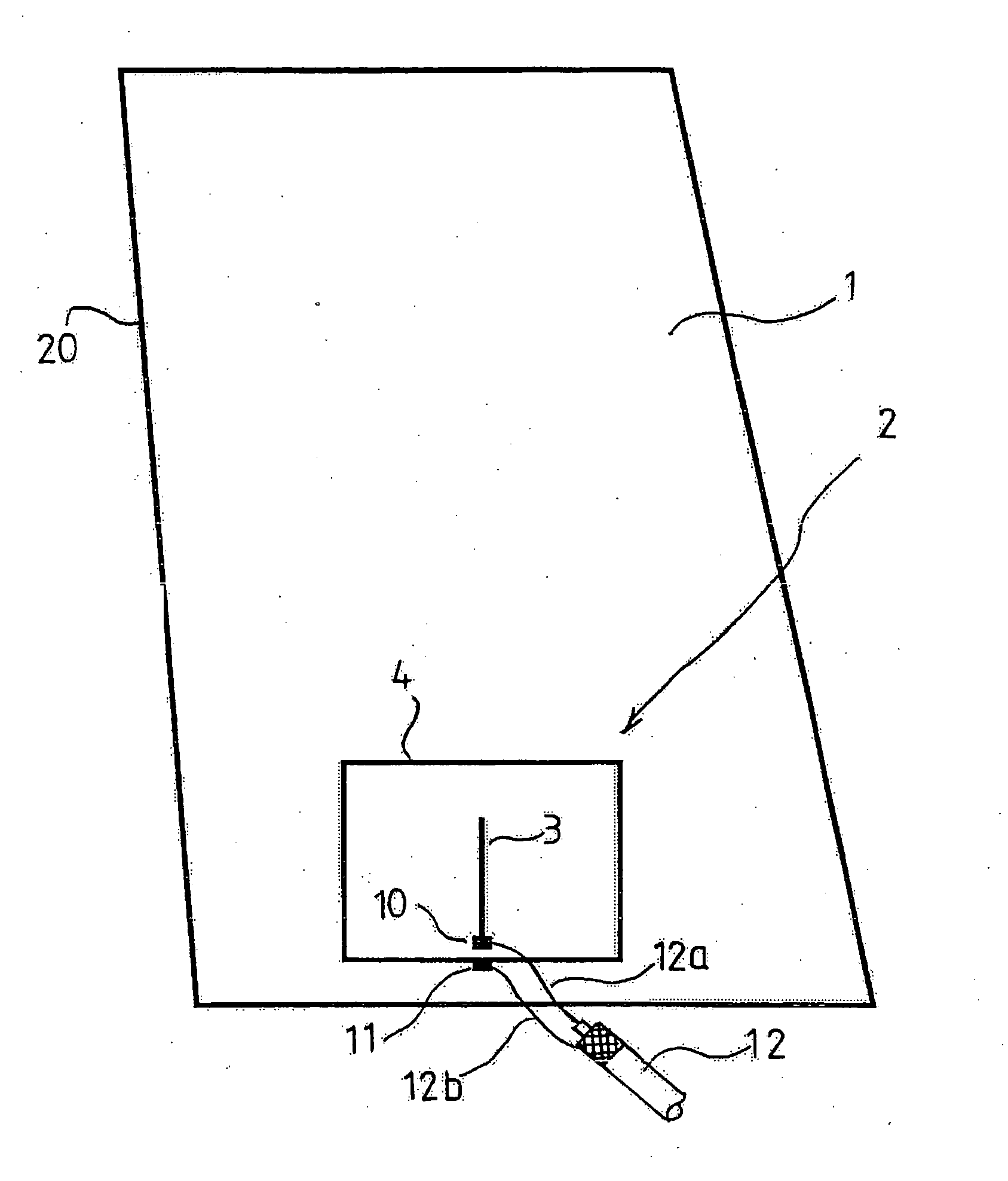
[0136]FIG. 1 is a view seen from the outside of a vehicle of an antenna pattern of the invention which is provided on a side window glass 1 of a vehicle.

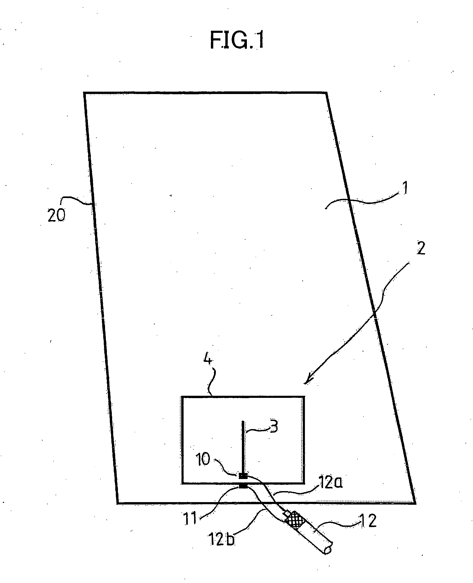
[0137] A pattern shown in FIG. 2 is such that a first element 3 and a second element 4 were printed and baked to a passenger compartment side of the glass 1 or a seal or sheet on which the pattern is printed was securely affixed to the surface of an insulating member such as a resin body and is such as to be used as an antenna for portable telephones with a frequency of 800 MHz band.

[0138] A first feeding point 10 and a second feeding point 11 were provided in such a manner that the second feeding point 11 was situated close to a lower portion of the first feeding point 10, and a perpendicular line, whose length corresponds to ¼ of the wavelength of radio wave to be transmitted and received, was extended perpendicularly upwards from the first feeding point 10, and this was made as the first element 3.

[0139] The antenna 2 is such ...

example 2

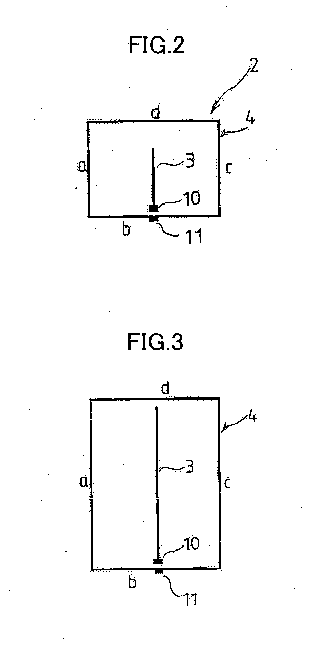
[0147] Example 2 is a modified example in which the pattern of Example 1 was modified such that the length of the first element 3 was modified to ¾ of the wavelength of radio wave to be transmitted and received, the full circumferential length of the second element 4 was to three wavelengths and the second element 4 was formed into a vertically elongated quadrangular shape as shown in FIG. 3, an antenna pattern so formed according to the invention being provided on a passenger compartment side of a sheet glass.

[0148] Namely, the length of the first element 3 was made to correspond to a line extended ¾ of the wavelength of the transmission and reception radio wave from the first feeding point 10 for the frequency of 800 MHz, that is, the length became 165 mm long, assuming that the wavelength compaction ratio of the glass plate in the frequency of 800 MHz is 0.6, and the first element 3 was provided perpendicularly so as to be a perpendicular line.

[0149] In addition, as to the seco...

example 3

[0154] Example 3 is also a modified example in which the pattern of Example 1 was modified such that the length of the first element 3 is modified to a length corresponding to ¼ of the wavelength of the transmission and reception radio wave, the full circumferential length of the second element 4 was to a length corresponding to one wavelength, and furthermore, the shape of the second element 4 was formed into a deformed quadrangular shape as shown in FIG. 4, an antenna pattern so formed being used as an antenna for portable telephones with a frequency bandwidth of 2 GHz band. The pattern so formed was printed and baked to a passenger compartment side of a sheet glass or a seal or sheet on which the pattern was printed was securely affixed to a passenger compartment side of a window glass 1 or the surface of an insulating member such as a resin body.

[0155] The second element 4 was formed into a quadrangular shape which have four angular corners at upper and lower and left and right...


PUM


Abstract

An antenna for vehicle, i.e. a wire antenna being arranged on the surface of the window glass of an automobile or the like, comprising a first element having a length extending from a first feeding point equal to any one of ¼, ¾ or 5/4 of the wavelength of a transmitting/receiving radio wave, and a second closed loop element having a length extending from a second feeding point, provided in the vicinity of the first feeding point, while surrounding the first element not shorter than one wavelength of the transmitting/receiving radio wave.

Description

TECHNICAL FIELD [0001] The present invention relates to a line antenna provided on the surface of a window glass or the surface of an insulating member of a movable body such as a vehicle, which is preferable for use in receiving FM radio broadcast waves, digital radio broadcast waves and television broadcast waves, as well as in transmitting and receiving radio waves of very-high-frequency range or higher such as of car telephones, portable telephones, personal radio communication equipment, commercial radio communication equipment and PHS (Personal Handy Phone System). BACKGROUND ART [0002] Conventionally, while rod antennas have been widely used as antennas for transmitting and receiving radio waves of car telephones and portable telephones and receiving television broadcast waves, since the construction of these rod antennas requires them to protrude from the vehicle body, there have been caused drawbacks that the protrusion of the antennas is not preferable from safety and aest...

Claims


Application Information

Patent Timeline
IPC IPC(8): H01Q1/32H01Q1/12
CPCH01Q1/1271H01Q1/22H01Q1/32H01Q7/04H01Q9/0407
Inventor FUJII, HIROYUKIUEMURA, MASASHI
Owner CENT GLASS CO LTD
Why Eureka
Try Eureka