Miniaturized printed ultra-wideband and bluetooth antenna

a printed ultra-wideband and bluetooth antenna technology, applied in the field of printed antennas, can solve the problems of affecting the timely upgrade of the system, the plurality of antennas occupying a lot of space, and the complexity of the system, so as to achieve the effect of reducing the area of the antenna, simple structure and easy implementation of the process

Active Publication Date: 2022-06-14
CHANGSHA CHIXIN SEMICON TECH CO LTD
View PDF14 Cites 0 Cited by
  • Summary
  • Abstract
  • Description
  • Claims
  • Application Information

AI Technical Summary

Benefits of technology

[0022]A miniaturized printed ultra wideband and Bluetooth antenna of an embodiment of the present invention comprises a first antenna element and a second antenna element, wherein the first antenna element has a rectangular shape with rounded and smoothed corners; the right side of the first antenna element comprises a first antenna body, and a rectangular notch is etched from the left side of the first antenna element; the left side of the second antenna element comprises a second antenna body, and the right side of the second antenna element has a plurality of bent portions arranged inside of the rectangular notch of the first antenna element. Since the plurality of bent portions of the second antenna element can be arranged inside of the rectangular notch of the first antenna element, the area of the antenna is greatly reduced, and the process design requirements for miniaturization of today's mobile terminals can still be met by covering both ultra wideband and Bluetooth wireless standard frequency bands.
[0023]Furthermore, the first antenna element has a rectangular shape with rounded and smoothed corners after asymmetrical miniaturization from a symmetrical circular or square radiating patch; and the rectangular notch is etched on the left side of the first antenna element; the structure is simple, and it is easy to implement the the process; and it is easy to be integrated with a circuit.
[0024]Further, the metal ground is arranged on the back side of the dielectric substrate; the metal ground is in the shape of a right-angled trapezoid; the printed monopole antenna plate is arranged on the front side of the dielectric substrate; and the metal ground and the printed monopole antenna are respectively arranged on the back side and the front side of the dielectric substrate, thereby better realizing an ultra wideband characteristic.
[0025]Further, the metal microstrip feed is arranged on the back side of the dielectric substrate, and the microstrip feeder is tapered from bottom to top to achieve impedance matching of the bottom and top antenna radiating patches of the microstrip feeder.
[0026]Further, the lower right-side end of the first antenna body is rounded and smoothed, thereby optimizing impedance matching and relaxing tolerances of antenna processing.
[0027]Further, the miniaturized printed ultra wideband and Bluetooth antenna of embodiments of the present invention has a width of only 1.75 cm and a printed planar area of only 5.75 cm2, with a compact structure. After performance tests, it has been shown to operate at the 2.33-2.54 GHz and 3.09-11 GHz bands and may cover both Bluetooth (2.4-5.485 GHz) and ultra wideband (3.1-10.6 GHz) communication bands.

Problems solved by technology

However, the plurality of antennas take up a lot of space and increase the complexity of the system.
In addition, the installation of a plurality of antennas also affects the timely upgrade of the system.

Method used


Image

  • Miniaturized printed ultra-wideband and bluetooth antenna
  • Miniaturized printed ultra-wideband and bluetooth antenna
  • Miniaturized printed ultra-wideband and bluetooth antenna

Examples


Embodiment Construction

[0039]In order to make the objectives, technical solutions, and advantages of embodiments of the invention clearer, the technical solutions in the embodiments of the invention will be described clearly and completely in conjunction with the accompanying drawings in the embodiments of the invention. Obviously, the described embodiments are part of the invention, rather than all of the embodiments. Based on the embodiments in the invention, all other embodiments obtained by a person skilled in the art without involving any inventive effort are within the scope of protection of the invention.

[0040]Hereinafter, embodiments of the present invention will be described in detail with reference to specific embodiments. The following specific embodiments may be combined with one another, and the same or similar concepts or processes may not be repeated in some embodiments.

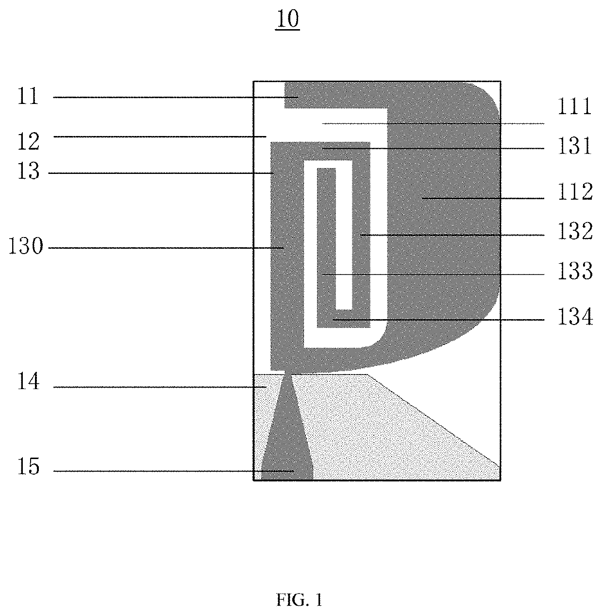
[0041]Based on the problems existing in the prior art, the embodiments of the present invention provide a miniaturized pri...


PUM


Abstract

The present invention provides a printed miniaturized ultra-wideband (UWB) and Bluetooth antenna, comprising a dielectric substrate, a printed monopole antenna plate, a metal ground and a metal microstrip feed, wherein the printed monopole antenna plate is arranged on the front side of the dielectric substrate; the printed monopole antenna plate comprises first and second antenna elements configured to operate in the ultra wideband communication band and operate in the Bluetooth communication band respectively, and the first antenna and second antenna elements share the common metal ground and the metal microstrip feed; the first antenna element has a rectangular shape with rounded and smoothed corners; the right side of the first antenna element comprises a first antenna body, and a rectangular notch is etched from the left side of the first antenna element; the left side of the second antenna element comprises a second antenna body, and the right side of the second antenna element has a plurality of bent portions; and the plurality of bent portions are arranged inside of the rectangular notch of the first antenna element. The antenna provided by the present invention is miniaturized, so that an antenna with a compact structure is achieved which can cover two wireless standard frequency bands.

Description

CROSS-REFERENCE TO RELATED APPLICATIONS[0001]This application is a U.S. Continuation Application which claims priority from PCT / CN2021 / 138451, filed Dec. 15, 2021, which claims priority from CN 202110539526.7, filed May 18, 2021, incorporated herein by reference in its entirety.TECHNICAL FIELD[0002]Embodiments of the present invention relate to the field of printed antennas, and more particularly to a miniaturized printed ultra-wideband and Bluetooth antenna.BACKGROUND ART[0003]Ultra-Wideband (UWB) is suitable for a wide range of wireless systems, and UWB can be traced back to telegraph systems including the transatlantic pulse signal transmission noted in 1901. The technology then finds some applications in radar, mainly for military purposes. In 2002, the U.S. Communications Commission adopted the regulations that the frequency band of 3.1-10.6 GHz was classified as commercial use and the frequency band of 22-29 GHz was classified as on-board radar system. Since then, UWB technolo...

Claims


Application Information

Patent Timeline
Patent Type & Authority Patents(United States)
IPC IPC(8): H01Q5/25H01Q9/42H01Q1/22H01Q1/38H01Q9/04
CPCH01Q5/25H01Q1/2291H01Q1/38H01Q9/045H01Q9/0421H01Q9/42H01Q5/371
Inventor LIU, JIANJUNHUANG, ZHEYANG
Owner CHANGSHA CHIXIN SEMICON TECH CO LTD
Why Eureka
Try Eureka