Ankle Tibia Plates

a technology of tibia and tibia, which is applied in the field of implants, can solve the problems of reducing the structural strength of the plate, increasing the risk of plate failure, and affecting the patient's comfort, so as to reduce the overall structural strength of the ankle plate and add structural strength

Active Publication Date: 2015-11-19
OSTEOMED
View PDF2 Cites 24 Cited by
  • Summary
  • Abstract
  • Description
  • Claims
  • Application Information

AI Technical Summary

Benefits of technology

[0011]Additionally, or alternatively, in some embodiments of the present disclosure, the second portion may include a central opening. The central opening may follow the contour of the outer edge of the second portion, and may include a middle bridge disposed within the central opening. Additionally, the middle bridge may be configured to provide additional fixation points for the ankle plate. The additional fixation points provided by the middle bridge may include at least one aperture disposed in a manner so as to receive and orient a respective bone fastener in a predetermined direction. Further, the middle bridge may provide additional structural strength to the ankle plate such that the thickness of the elongated first portion and the thickness of the second portion of the ankle plate may be reduced without reducing the overall structural strength of the ankle plate.

Problems solved by technology

However, a thick plate often causes discomfort to the patient since is attached directly to the outer surface of the bone under the skin.
A thin plate, while possibly being more comfortable for the patient, reduces the structural strength of the plate, thus making it weaker.
A weaker ankle plate is more likely to fail under the stress of patient activity, and therefore exposes the patient to serious injury.
Such modifications to the ankle plate, however, result in a reduction in the structural strength of the ankle plate.

Method used


Image

  • Ankle Tibia Plates
  • Ankle Tibia Plates
  • Ankle Tibia Plates

Examples


Embodiment Construction

[0022]The detailed description set forth below, in connection with the appended drawings, is intended as a description of various configurations and is not intended to limit the scope of the disclosure. Rather, the detailed description includes specific details for the purpose of providing a thorough understanding of the inventive subject matter. It will be apparent to those skilled in the art that these specific details are not required in every case and that, in some instances, well-known structures and components are shown in block diagram form for clarity of presentation. Likewise, the terminology used herein is for the purpose of describing particular embodiments only, and is not intended to limit the invention

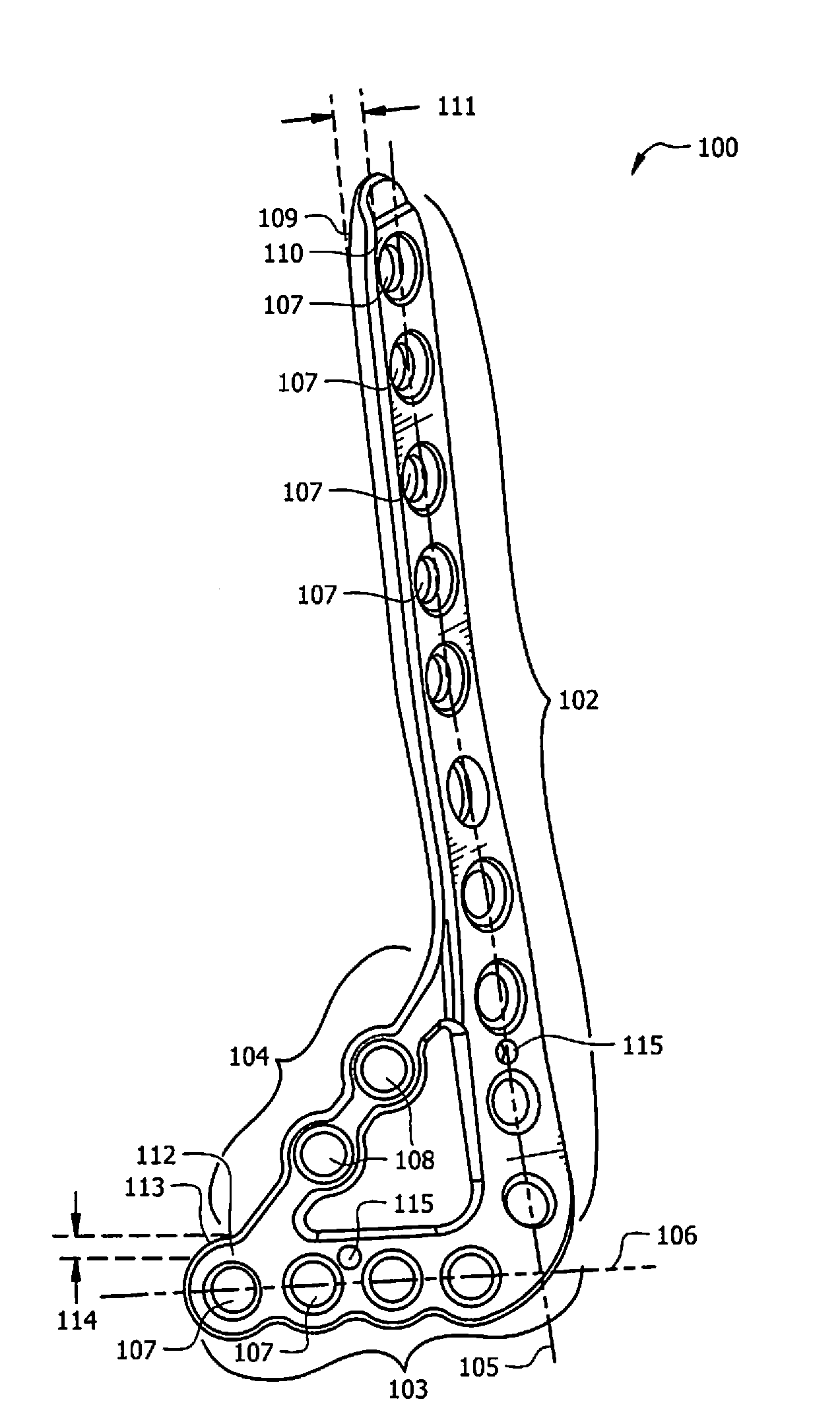
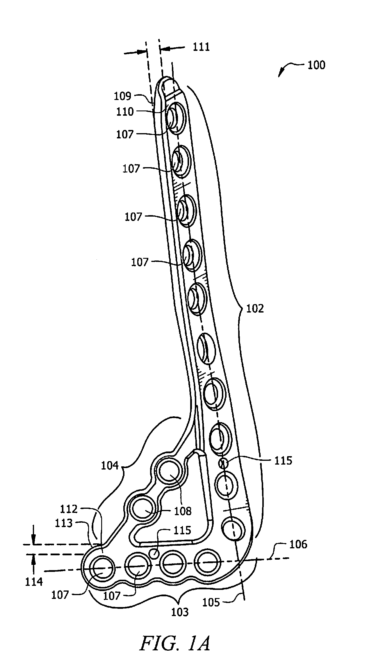
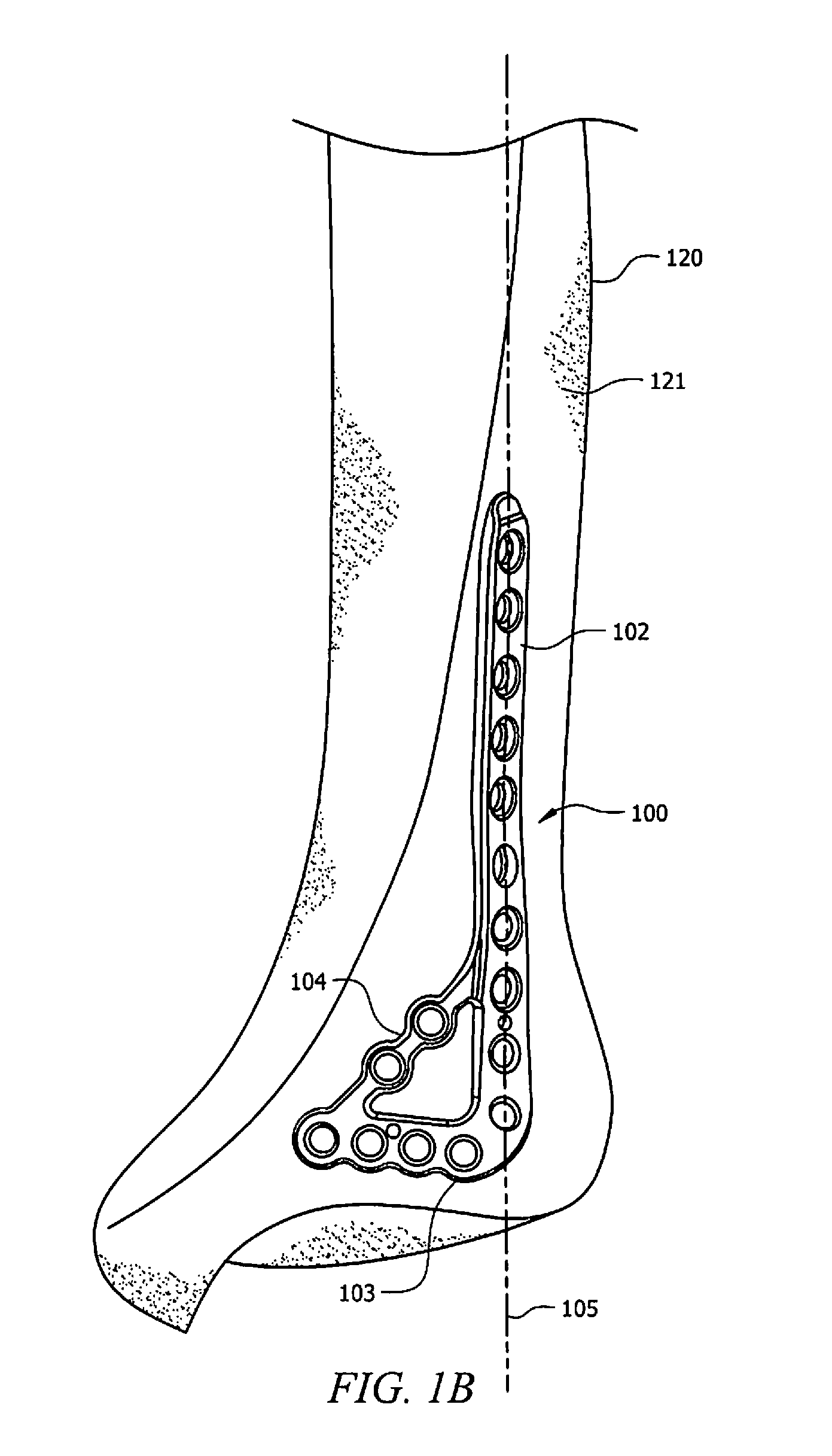
[0023]Referring to FIG. 1A, an illustrative embodiment of an ankle plate for attaching to the anterior lateral surface of a tibia bone is shown and designated 100. FIG. 1B shows a representative example of ankle plate 100 attached to tibia bone 120. In the illustrated emb...


PUM


Abstract

Implant devices for the internal fixation of fractured bones, and more particularly to ankle plates for the tibia bone are disclosed and include an anterolateral tibia plate having an L-shaped body including a proximal portion defining a longitudinal axis, and a distal portion defining a traverse axis, and having a support bridge connected between the proximal portion and the distal portion. Implant devices disclosed also include an anterior tibia plate having an elongated first portion, a second portion that widens outward with respect to the elongated first portion, and a plurality of removable tabs attached to the outer edge of the second portion. Implant devices disclosed also include a medial tibia plate having an elongated shaft with a proximal portion and a distal portion. The distal portion is configured to extend proximate to a base of medial malleolus, and has a curvature with respect to a longitudinal axis defined by the elongated shaft. The distal portion may include a plurality of removable tabs. The removable tabs may be disposed to define an opening between the removable tabs to orient a bone fastener into a bone.

Description

TECHNICAL FIELD[0001]The present application relates to implant devices for the internal fixation of fractured bones, and more particularly to ankle plates disposed on the tibia.BACKGROUND[0002]A fractured or broken ankle can include a break or fracture of the tibia bone. Fractures or breaks of the tibia bone are often repaired by holding bone fragments together to achieve fusion. Generally, this is accomplished by the use of ankle plates that are attached directly to the outer surface of the bone via a surgical procedure.[0003]As with any other bone fracture, the structural strength of a plate used to repair an ankle fracture is of paramount importance. Strength of a plate is generally proportional to the thickness of the plate. However, a thick plate often causes discomfort to the patient since is attached directly to the outer surface of the bone under the skin. A thin plate, while possibly being more comfortable for the patient, reduces the structural strength of the plate, thus...

Claims


Application Information

Patent Timeline
Patent Type & Authority Applications(United States)
IPC IPC(8): A61B17/80
CPCA61B17/8061A61B17/80A61B17/8057A61B17/8085
Inventor EARLY, JOHNBRAGE, MICHAEL E.POMEROY, GREGORYCARPENTER, BRIANMILLER, DOUGLAS W.
Owner OSTEOMED
Why Eureka
Try Eureka