
Ablation systems, probes, and methods for reducing radiation from an ablation probe into the environment

a radiation reduction and probe technology, applied in the field ofablation systems, can solve the problems of routine observation of thermal damage to most types of normal cells, unwanted heating of healthy tissue, non-invasive procedures using microwave energy, etc., and achieve the effect of reducing or eliminating radiation

Inactive Publication Date: 2015-11-19
COVIDIEN LP
View PDF0 Cites 0 Cited by
  • Summary
  • Abstract
  • Description
  • Claims
  • Application Information

AI Technical Summary

Benefits of technology

The present patent provides an ablation system that reduces harmful radiation from the probe and requires minimal changes to the generator. The system includes a probe with a radiating portion that delivers energy to tissue, and a fluid circuit module with two fluid conduits. A first fluid helps to transmit energy, while a second fluid prevents energy from reaching the tissue or the environment. The system also includes a check valve to prevent fluid from flowing in the wrong direction. Furthermore, the probe has a retractable sheath to prevent energy from leaking out. This system allows for safer and effective ablation procedures with existing generators.

Problems solved by technology

However, this non-invasive procedure may result in unwanted heating of healthy tissue.
Thus, non-invasive procedures that use microwave energy require precise temperature control.
However, at slightly elevated temperatures above the approximate range of 43° C. to 45° C., thermal damage to most types of normal cells is routinely observed.
Therefore, if the generator is still powering the probe after it is removed from tissue, individuals near the probe may be unnecessarily exposed to microwave energy.

Method used


Image

  • Ablation systems, probes, and methods for reducing radiation from an ablation probe into the environment
  • Ablation systems, probes, and methods for reducing radiation from an ablation probe into the environment
  • Ablation systems, probes, and methods for reducing radiation from an ablation probe into the environment

Examples


Embodiment Construction

[0039]Particular embodiments of the present disclosure are described below with reference to the accompanying drawings.

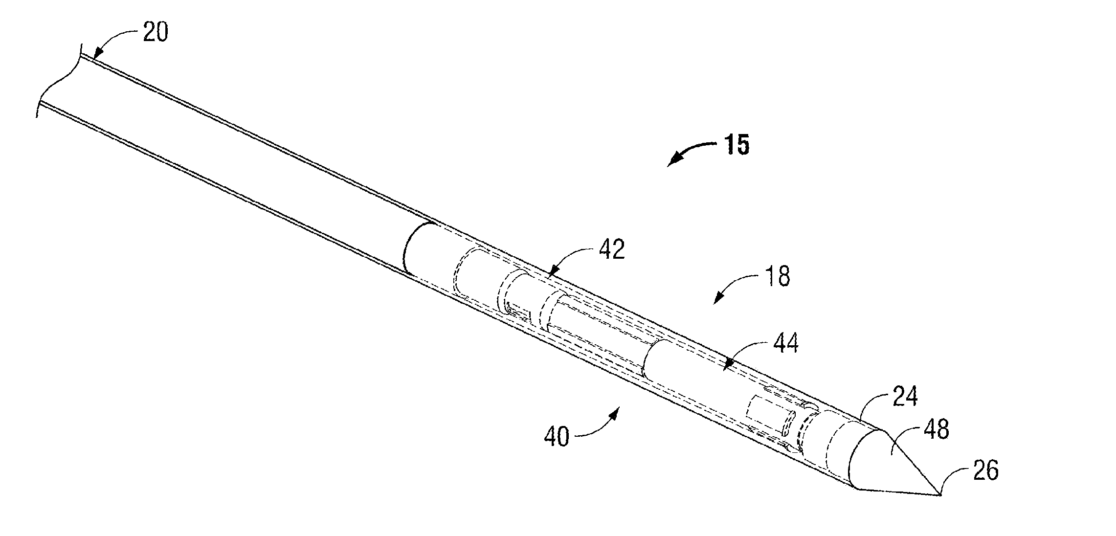
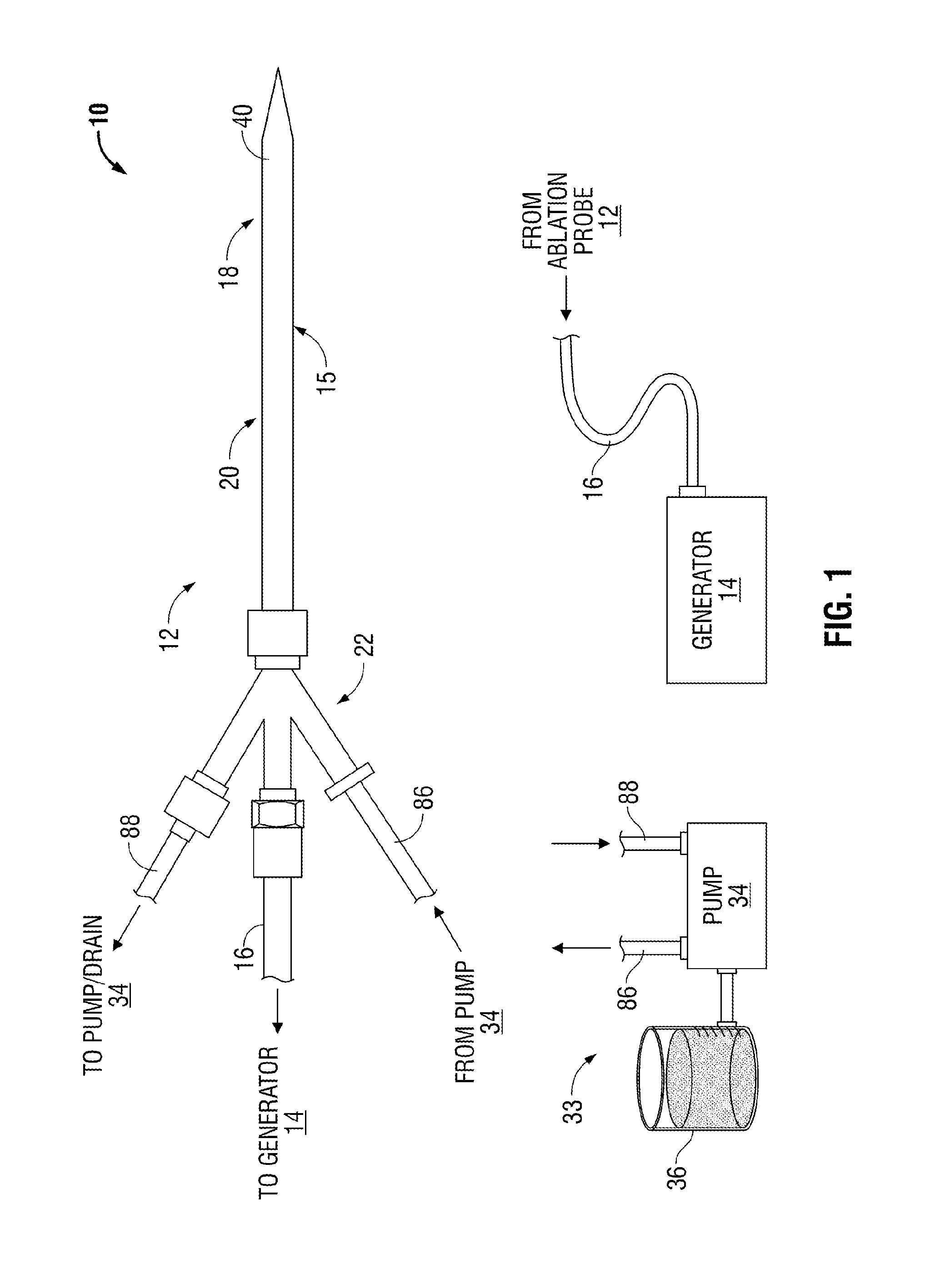
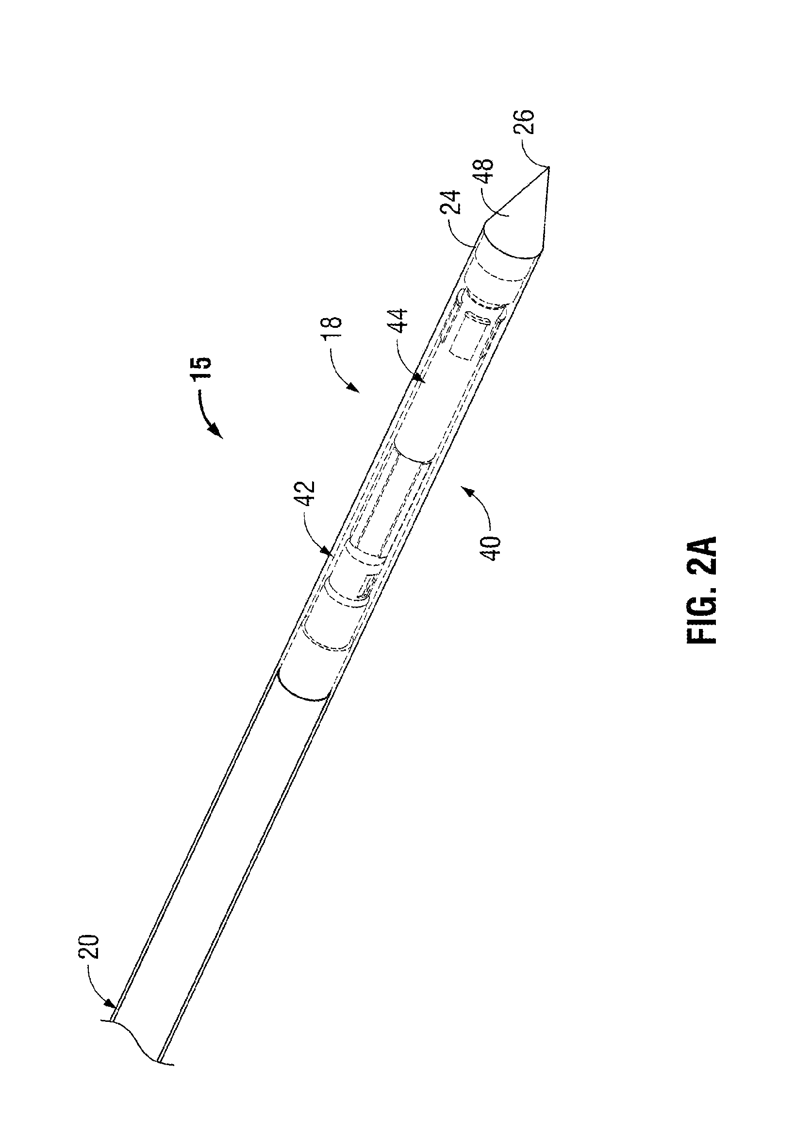
[0040]Generally, the present disclosure relates to systems and corresponding methods for reducing or eliminating energy that radiates from ablation probes into the environment. These systems and corresponding methods require few or no changes to the electrosurgical generator that supplies power to the ablation probe. The systems include various shielding mechanisms for shielding individuals from unnecessary energy radiating from the ablation probe when it is removed from tissue.

[0041]The ablation systems according to the present disclosure include a retractable sheath or shield that shields at least the radiating portion of the ablation probe to reduce or eliminate the radiation of energy (e.g., microwave energy) into the environment. The retractable sheath may include conduits through which a shielding fluid flows to shield the radiating portion of the ablation pro...


PUM


Abstract

The ablation systems, ablation probes, and corresponding methods according to the present disclosure reduce or eliminate energy radiating from an ablation probe into the environment. Some ablation probes include a retractable sheath that shields at least the radiating portion of the ablation probe. The retractable sheath and / or the ablation probe may include conduits through which a fluid may flow to shield the radiating portion and to drive the retractable sheath to an extended state. Other ablation probes include apertures defined in the probe walls through which the fluid can flow to expand a balloon surrounding the radiating portion. Yet other ablation probes include a thermal indicator to indicate the temperature of the ablation probe to a user. The ablation systems include fluid circuits and associated mechanical controls for varying the contents and / or flow rate of the fluid provided to the radiating portion of the ablation probe.

Description

BACKGROUND[0001]1. Technical Field[0002]The present disclosure generally relates to ablation systems. More particularly, the present disclosure is directed to ablation systems, probes, and methods for reducing or eliminating energy radiating from an ablation probe into a surgical environment.[0003]2. Background of Related Art[0004]In the treatment of diseases such as cancer, certain types of cancer cells have been found to denature at elevated temperatures (which are slightly lower than temperatures normally injurious to healthy cells.) These types of treatments, known generally as hyperthermia therapy, typically utilize electromagnetic radiation to heat diseased cells to temperatures above 41° C., while maintaining adjacent healthy cells at lower temperatures where irreversible cell destruction will not occur. Other procedures using electromagnetic radiation to heat tissue include ablation and coagulation. These procedures are typically done to denature or kill the targeted tissue....

Claims


Application Information

Patent Timeline
Patent Type & Authority Applications(United States)
IPC IPC(8): A61B18/18
CPCA61B2018/00023A61B18/1815A61B18/1477A61B2018/00011A61B2018/00017A61B2018/00196A61B2018/00458A61B2018/00577A61B2018/00791A61B2018/00809A61B2018/1425A61B2018/1475A61B2018/1869A61B2018/1892
Inventor REID, JR., WILLIAM O.
Owner COVIDIEN LP
Learn More