Pen Needle Assembly

a needle and needle body technology, applied in the field of pen needles, can solve the problems of not reliably piercing, insufficient penetration depth, and insufficient indication to the user that the needle has reached the optimal penetration depth, so as to reduce the use of materials, improve patient comfort, and reduce the effect of cos

Active Publication Date: 2015-11-19
EMBECTA CORP
View PDF4 Cites 15 Cited by
  • Summary
  • Abstract
  • Description
  • Claims
  • Application Information

AI Technical Summary

Benefits of technology

[0008]The inventors herein have explored ways to make lower cost pen needles with reduced materials usage while retaining the popular functional features of current products. In one aspect, the disclosure pertains to a pen needle which has a plastic non-patient end cannula which may be molded in one piece with the hub. This affords the advantage that a larger diameter cannula may be used on the non-patient end to provide strength to pierce the septum of the medication cartridge, while a lighter gauge stainless steel needle is used on the patient end for increased patient comfort during an injection.

Problems solved by technology

A problem exists in that thinner gauge needles which may be preferred for patient comfort do not reliably pierce the septum of the medication compartment when the pen needle is installed on the medication pen.
Another drawback of the commonly available pen needles is that they do not provide the user with an indication that the needle has reached the optimal penetration depth.
The user relies on subjective sensation of pain when performing an injection to determine the depth of penetration, which may result in too much or too little penetration.
An injection that is too deep may cause unnecessary pain when the needle is pressed too hard against the body, while an injection that is not deep enough may result in improper dosing.

Method used


Image

  • Pen Needle Assembly
  • Pen Needle Assembly
  • Pen Needle Assembly

Examples


Embodiment Construction

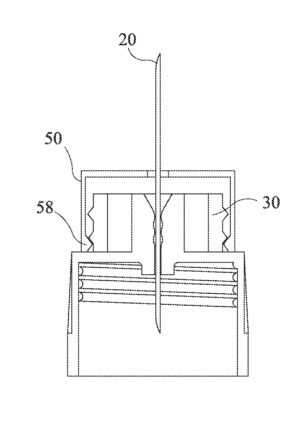
[0033]As used herein, the “distal” direction is in the direction of the injection site, and the “proximal” direction is the opposite direction. The “axial” direction is along, or parallel to, the longitudinal axis of the syringe body. The cannula is generally arranged axially in a medication pen. “Radially” is a direction perpendicular to the axial direction. Thus, “radially inward” generally means closer to the needle. The accompanying figures are schematic and not to scale.

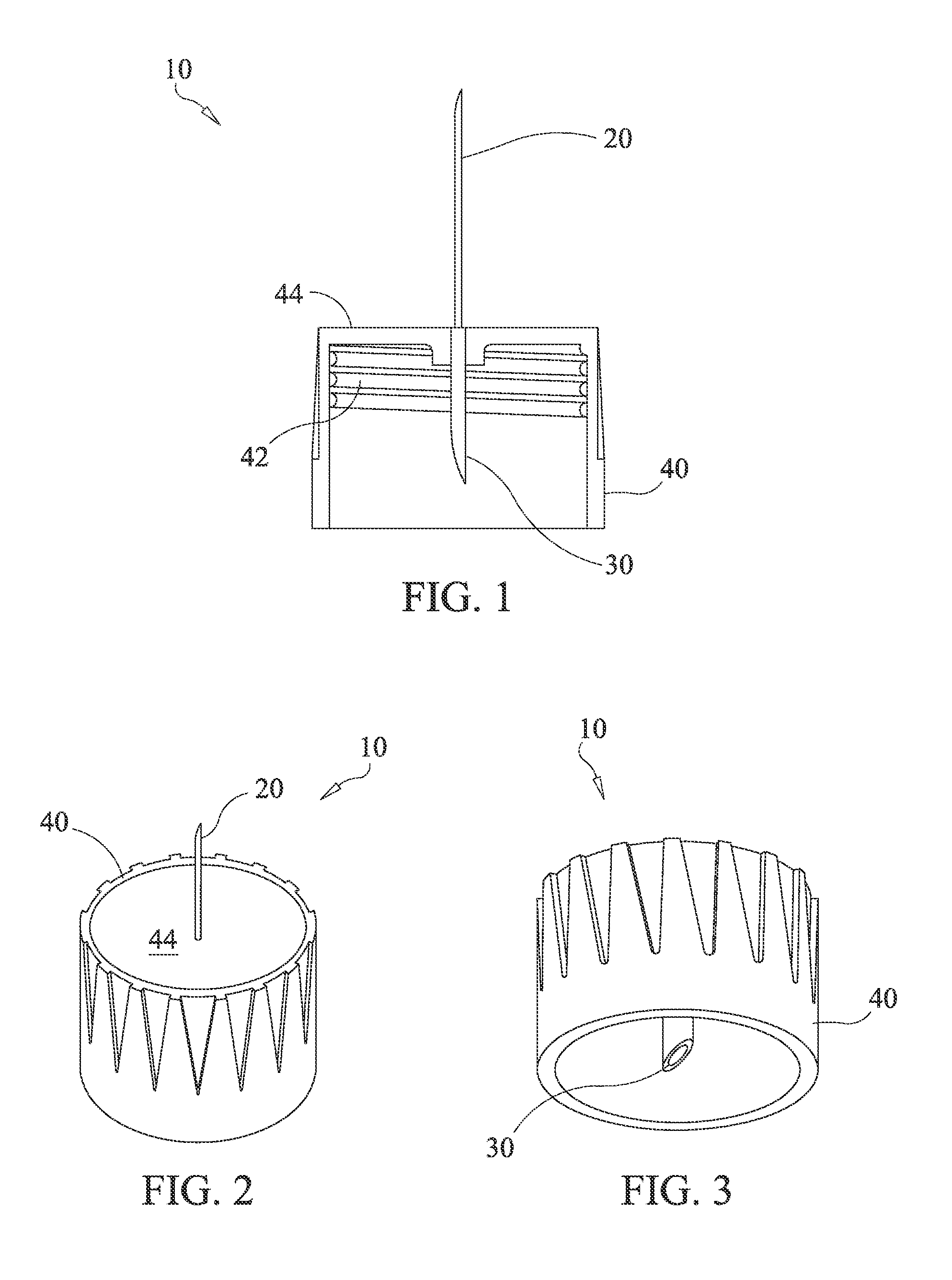
[0034]FIG. 1 is a cross section of a disposable pen needle 10 with a plastic non-patient end cannula 30. The plastic non-patient end cannula 30 may be molded as part of the hub 40, which is adapted for attachment to a medication pen, or the like, via threads 42 or other attachment means known in the art, such as cooperating detents and protrusions which snap together. The patient-end of the needle is a stainless steel cannula 20 with a single point (similar to a syringe needle) which can be attached to the hub 4...


PUM


Abstract

A pen needle is provided with a plastic non-patient end. Since the non-patient end needle does not contact the patient, the needle can be formed with a larger diameter, permitting more secure attachment to a medication pen and greater medication flow from the cartridge through the cannula. In addition, a two-part hub construction comprising a needle bearing sub assembly and an adapter for attachment to the pen body may be used to lower materials volume and costs, and reduce sharps disposal. In embodiments, a hub according to the invention may be provided with a shield that provides an audible and/or tactile indication when full penetration depth of the needle is achieved. Windows on the shield may reveal a color band on the hub at the full-penetration depth position to provide the user with a visual indication that the pen needle has been used.

Description

[0001]This application claims the benefit of U.S. Provisional Application No. 61 / 746,108, filed Dec. 26, 2013; U.S. Provisional Application No. 61 / 746,109, filed Dec. 26, 2013; and U.S. Provisional Application No. 61 / 746,103, filed Dec. 26, 2013, all of which are incorporated by reference.BACKGROUND OF THE INVENTION[0002]1. Field of the Invention[0003]The invention is directed to a pen needle which may be installed on a drug delivery device, such as a medication pen, including modifications that make the pen needle more cost effective and user friendly.[0004]2. Description of the Related Art[0005]Pen needles are widely used in medication delivery systems for self-administered injectable drugs. The pen needles that are commonly used have a single stainless steel cannula extending through the needle-bearing hub. The non-patient end of the needle pierces the closure of the drug storage compartment of the medication pen while the patient end of the needle is adapted for insertion into t...

Claims


Application Information

Patent Timeline
Patent Type & Authority Applications(United States)
IPC IPC(8): A61M5/34A61M5/32A61M5/46A61M5/00
CPCA61M5/346A61M5/002A61M5/3293A61M5/347A61M5/329A61M2205/581A61M5/46A61M5/3286A61M2205/582A61M2205/584A61M2206/00A61M5/345A61M5/5086A61M2205/583A61B5/150175A61B5/150183A61B5/150198A61B5/15019
Inventor BATES, JAMESBANIK, ROBERTRAJ, ABHIJITSINH S.HERR, JOSHUABRIZZOLARA, JOSEPHLIMAYE, AMIT
Owner EMBECTA CORP
Why Eureka
Try Eureka