Method for manufacturing sensor intermediate product and method for manufacturing sensor

a technology of manufacturing sensor and intermediate product, which is applied in the direction of instruments, electrolytic capacitors, material analysis, etc., can solve problems such as element breakage, and achieve the effect of preventing sensor element breakag

Active Publication Date: 2015-11-19
NGK SPARK PLUG CO LTD
View PDF1 Cites 5 Cited by
  • Summary
  • Abstract
  • Description
  • Claims
  • Application Information

AI Technical Summary

Benefits of technology

[0028]The present invention can prevent breakage of the sensor element, which breakage would otherwise occur when the filling member for fixing the sensor element inside the metallic shell is disposed in the metallic shell.

Problems solved by technology

Therefore, if a portion of the talc ring has a shape-related defect caused by, for example, chipping of the talc ring, the stress acting on the sensor element 21 through the wall surface of the insertion hole of the talc ring becomes non-uniform, and a shearing stress acts on the sensor element 21, which may result in breakage of the element.

Method used


Image

  • Method for manufacturing sensor intermediate product and method for manufacturing sensor
  • Method for manufacturing sensor intermediate product and method for manufacturing sensor
  • Method for manufacturing sensor intermediate product and method for manufacturing sensor

Examples


Embodiment Construction

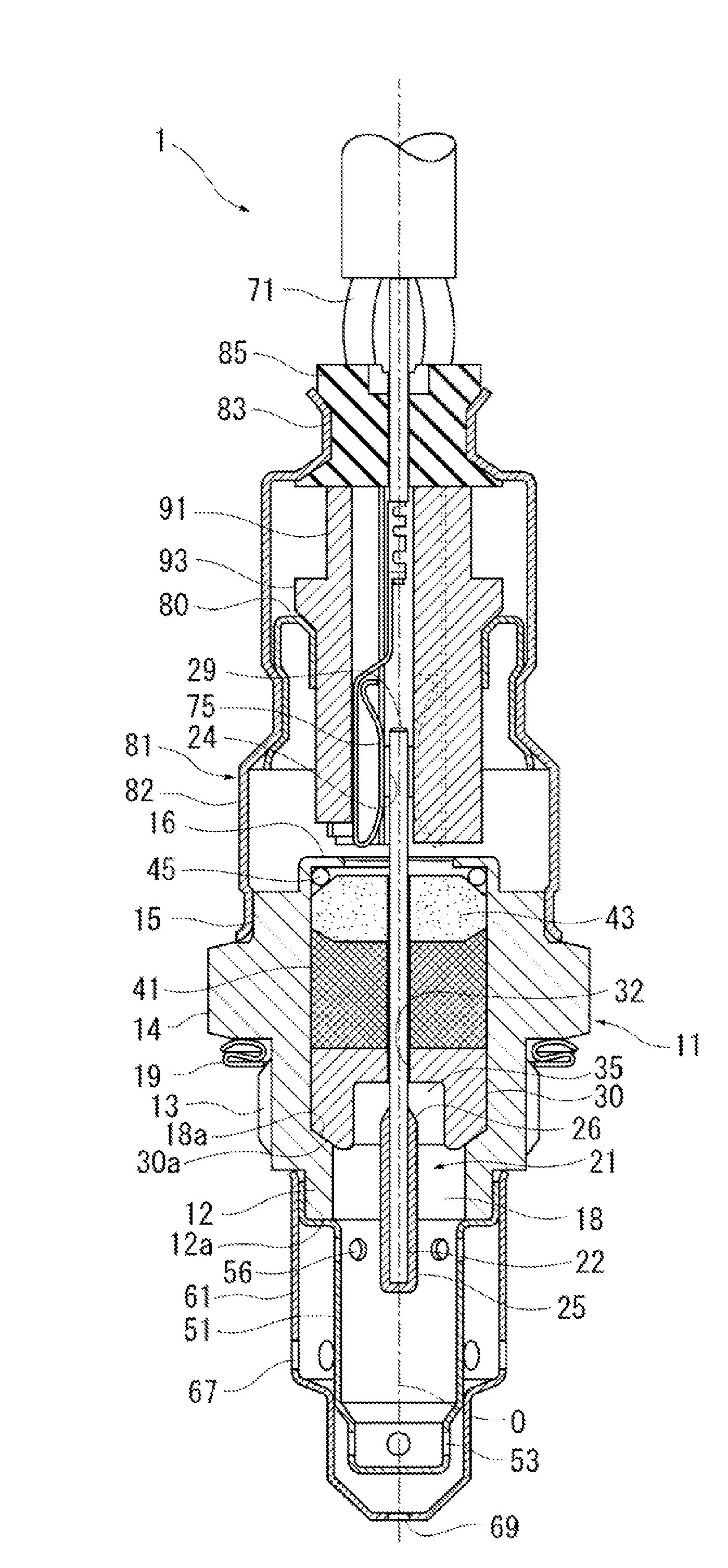
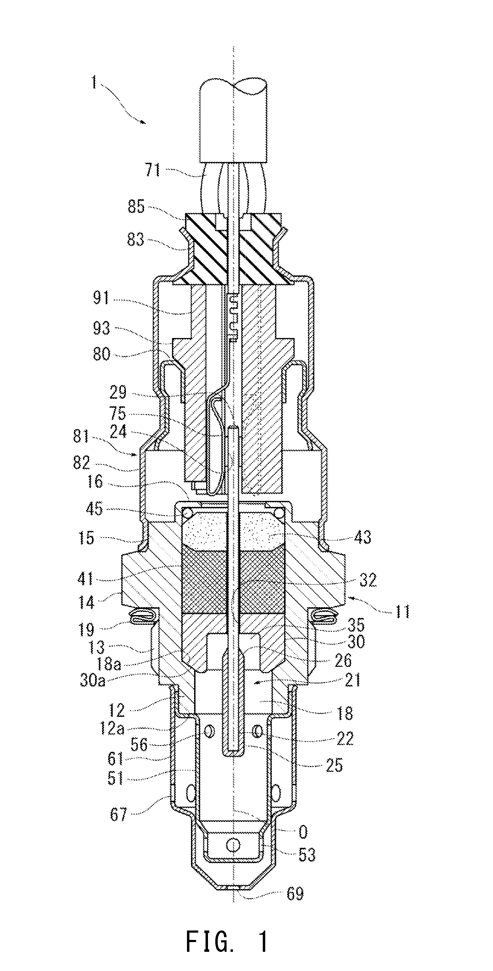
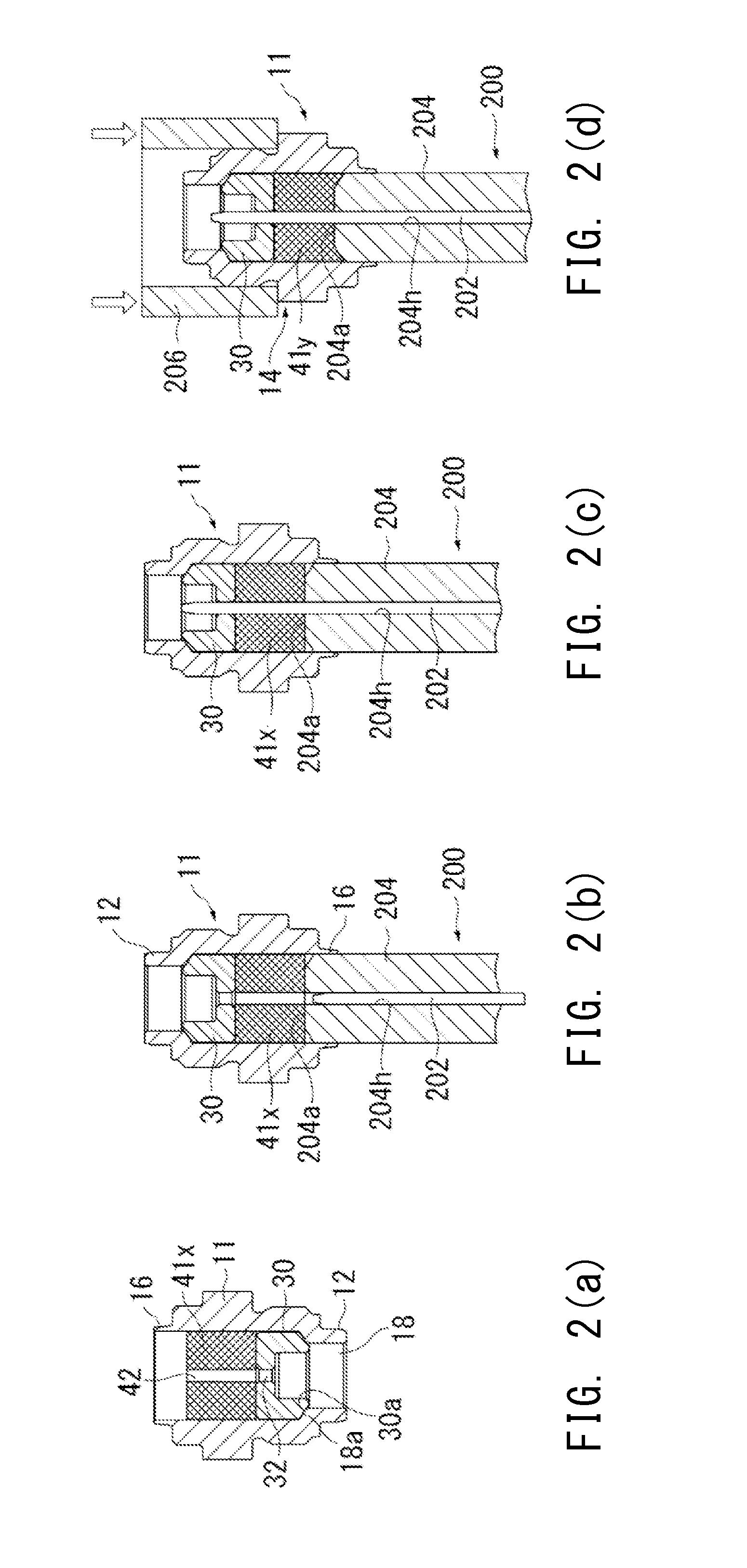
[0035]An embodiment of the present invention will now be described. In the following description, a term “method for manufacturing a sensor intermediate product” and a term “method for manufacturing a sensor” will be used when necessary. Steps up to a main compression step correspond to the “method for manufacturing a sensor intermediate product,” and all the steps, including an assembly step of fixing a protection sleeve 81 (see FIG. 4) to the sensor intermediate product after the main compression step, correspond to the “method for manufacturing a sensor.” For example, in the present embodiment, after a sensor intermediate product is manufactured by the steps shown in FIGS. 2(a) through 2(g), the protection sleeve 81 (semi-assembly 102) is fixed to a rear end portion of a metallic shell 11, whereby a gas sensor 1 is manufactured as shown in FIGS. 3 and 4. Accordingly, the steps shown in FIGS. 2(a) through 2(g) correspond to the “method for manufacturing a sensor intermediate produ...


PUM

PropertyMeasurementUnit
thicknessaaaaaaaaaa
circumferenceaaaaaaaaaa
pressureaaaaaaaaaa

Abstract

A method for manufacturing a sensor intermediate product includes: disposing a tubular holder and a tubular compact in a tubular metallic shell, and inserting a metallic pin into a first insertion hole of the holder and a second insertion hole of the compact; compressing the compact so as to form a filling member intermediate having a shape which brings the filling member intermediate into pressure contact with the inner wall surface of the metallic shell and allows removal of the metallic pin from the second insertion hole; pulling out the metallic pin from the first insertion hole and the second insertion hole; inserting a sensor element into the first insertion hole and the second insertion hole; and compressing the filling member intermediate to thereby form a filling member which fixes the sensor element inside of the metallic shell.

Description

CROSS REFERENCE TO RELATED APPLICATIONS[0001]The present application claims priority from Japanese Patent Application No. 2014-099529, filed on May 13, 2014, and Japanese Patent Application No. 2015-025007, filed on Feb. 12, 2015, the disclosures of which are herein incorporated by reference in their entirety.BACKGROUND OF THE INVENTION[0002]1. Field of the Invention[0003]The present invention relates to a method for manufacturing a sensor intermediate product having a sensor element for detecting the concentration of a gas to be detected, and to a method for manufacturing a sensor using the sensor intermediate product.[0004]2. Description of Related Art[0005]A known gas sensor for detecting the concentration of oxygen or NOx contained in exhaust gas discharged from an automobile or the like has a sensor element including a solid electrolyte member.[0006]Such a gas sensor is known to have a structure in which a sensor element is inserted into a tubular metallic shell (housing) to be...

Claims


Application Information

Patent Timeline
Patent Type & Authority Applications(United States)
IPC IPC(8): G01N27/407G01N27/409
CPCG01N27/4077Y10T29/42G01N27/409G01N27/4078Y10T29/49908Y10T29/49904G01N27/4074
Inventor TAHIRA, DAISUKENODA, KEIICHIITO, SHINGOOKADA, ATSUNORIYAMADA, YUICHI
Owner NGK SPARK PLUG CO LTD
Why Eureka
Try Eureka