Sealed Cartridge for an Aerosol Delivery Device and Related Assembly Method

a technology of aerosol precursor and cartridge, which is applied in the direction of lighting and heating apparatus, tobacco, heating types, etc., can solve the problems of delivering large quantities of incomplete combustion and pyrolysis products, and the aerosol precursor composition may be prone to leakage from the cartridge, so as to reduce the empty volume and reduce the empty volume

Active Publication Date: 2015-11-26
RAI STRATEGIC HLDG INC
View PDF10 Cites 299 Cited by
  • Summary
  • Abstract
  • Description
  • Claims
  • Application Information

AI Technical Summary

Benefits of technology

[0005]In some embodiments the cartridge may further include a reservoir substrate in the reservoir compartment. The reservoir substrate may be partially wrapped around the flow director such that a gap is defined between first and second ends thereof. The reservoir substrate may be at least partially wrapped about the flow director and engaged with a plurality of protrusions defined by the flow director and extending therefrom. The flow director may define a recess. The recess may define a channel between the flow director and the reservoir substrate. In some embodiments the cartridge may further include at least one heating terminal molded into the flow director and extending to a connector end of the base. The cartridge may additionally include an electronic control component positioned within the electronics compartment and a control component terminal extending from the electronic control component to a connector end of the base. The base may define a deformable rib configured to seal against an inner surface of the outer body. The flow director may define a deformable rib configured to seal against an inner surface of the outer body.
[0006]In some embodiments the flow director may be welded to the outer body. The flow director may also be welded to the base. The cartridge may additionally include a one-way valve configured to resist flow of air from the flow director through the base. The one-way valve may be selected from a group consisting of a flap valve and a cross-valve. The one-way valve may be positioned in the electronics compartment. The cartridge may further include a mouthpiece coupled to the outer body at an end thereof opposite from the base. The mouthpiece may define an extension configured to reduce an empty volume within the outer body. A spacer may be positioned between the mouthpiece and the atomizer. The spacer may be configured to reduce an empty volume within the outer body. The mouthpiece may include a lip defining a channel. The lip and the channel may extend around an aperture defined through the mouthpiece.

Problems solved by technology

Many of those devices purportedly have been designed to provide the sensations associated with cigarette, cigar, or pipe smoking, but without delivering considerable quantities of incomplete combustion and pyrolysis products that result from the burning of tobacco.
However, the aerosol precursor composition may be prone to leak from the cartridge, particularly during filling of the cartridge.

Method used


Image

  • Sealed Cartridge for an Aerosol Delivery Device and Related Assembly Method
  • Sealed Cartridge for an Aerosol Delivery Device and Related Assembly Method
  • Sealed Cartridge for an Aerosol Delivery Device and Related Assembly Method

Examples


first embodiment

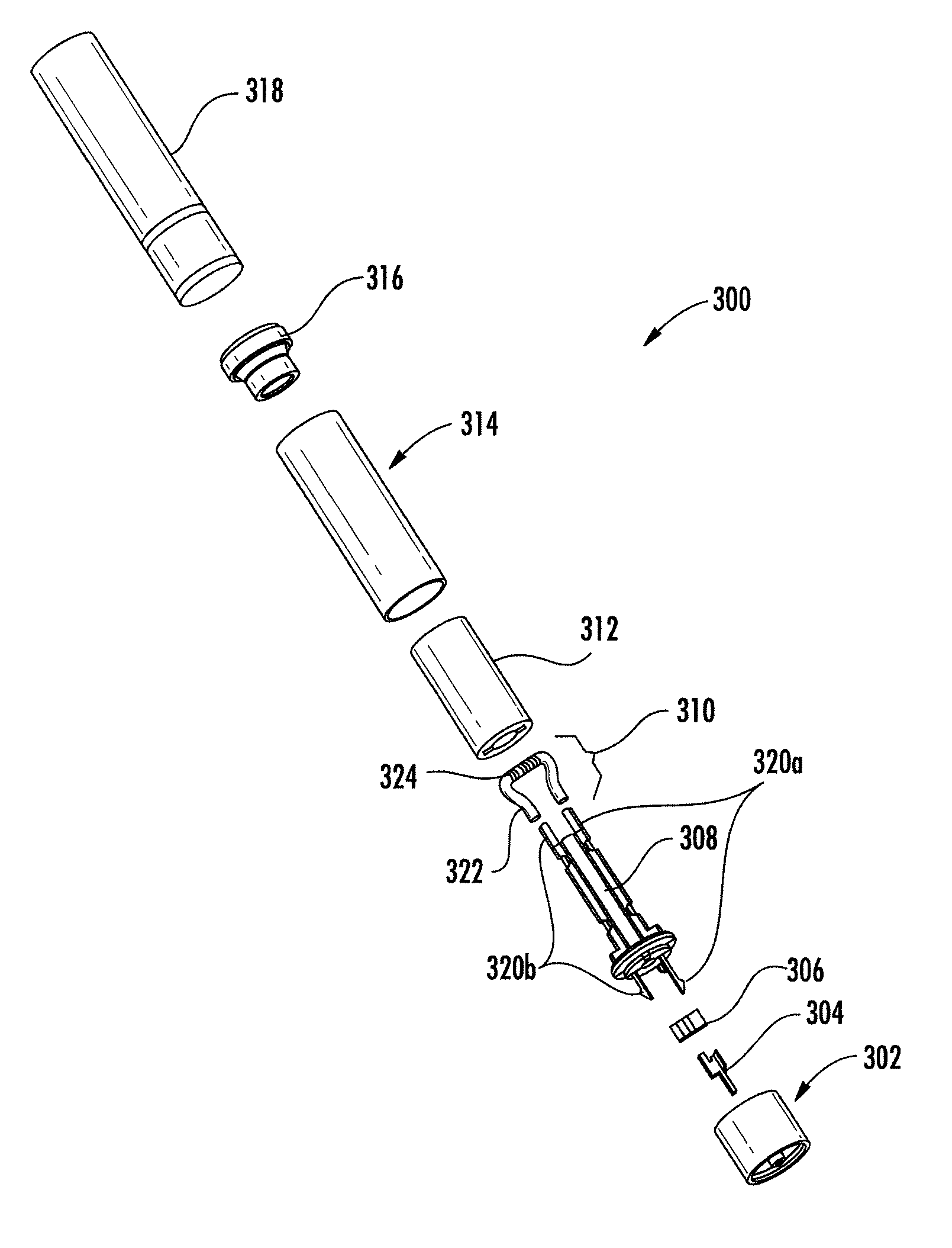
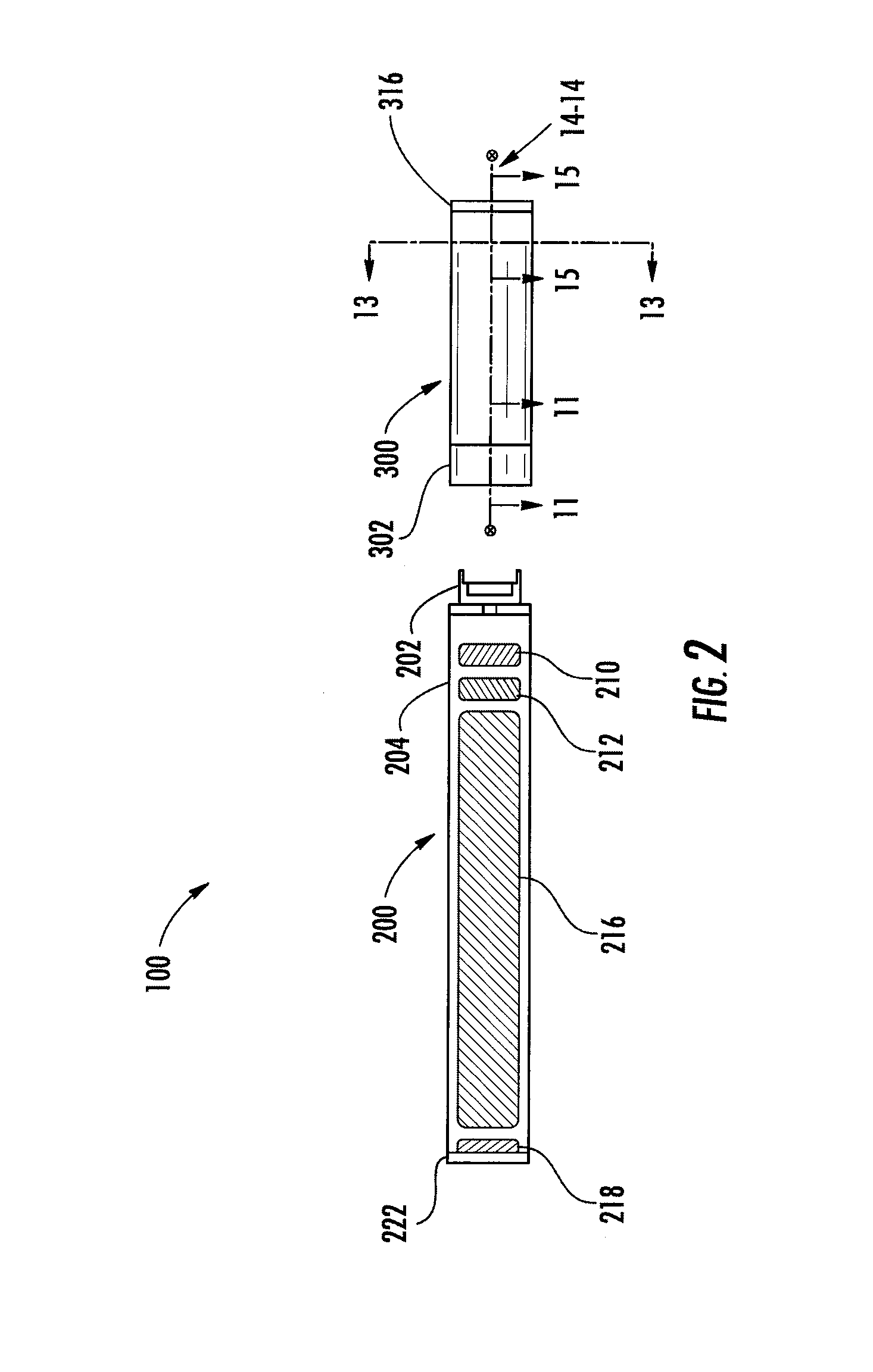
[0085]FIG. 11 illustrates a partial sectional view through the cartridge 300′ along line 11-11 from FIG. 2, wherein the reservoir substrate (see, e.g., FIG. 3) is hidden for clarity purposes, following coupling of the outer body 314 thereto. As illustrated, in some embodiments the outer body 314 may be directly coupled to the base 302. As further illustrated in FIG. 11, in some embodiments the outer body 314 may be directly coupled to the flow director 308. In other words, the outer body 314 may directly contact the base 302 and the flow director 308.

[0086]The flow director 308 and the outer body 314 may define a first compartment 376. In particular, the flow director 308 may contact the outer body 314 such that the flow director and the outer body collectively define and at least partially surround the first compartment 376. In some embodiments the first compartment 376 may be configured to receive the reservoir substrate 312. Accordingly, the first compartment 316 may also be refe...

second embodiment

[0102]For example, FIG. 12 illustrates a partial sectional view through the cartridge 300″ along line 11-11 from FIG. 2. In the embodiment of the cartridge 300″ illustrated in FIG. 12, the base 302 is indirectly coupled to the outer body 314 and other sealing configurations are employed. In this regard, in the embodiment of the cartridge 300″ illustrated in FIG. 12, the flow director 308 is coupled to the outer body 314. Further, the base 302 is coupled to the flow director 308. More particularly, the outer body 314 and the base 302 are directly coupled to the base portion 326 of the flow director 308. Accordingly, the base 302 may be indirectly coupled to the outer body 314 via direct coupling with the flow director 308.

[0103]As illustrated, in one embodiment the base portion 326 of the flow director 308 may extend to define a shape and size corresponding to a size and shape of an outer surface 314d of the outer body 314 and / or an outer surface 302d of the base 302. For example, in...


PUM


Abstract

The present disclosure relates to an aerosol delivery device. The aerosol delivery device may include a control body and a cartridge. The cartridge may include a base, a flow director, an outer body, a reservoir substrate, an outer body, and a mouthpiece. Heating elements may be molded into the flow director. The flow director may be welded to the base and the outer body, or the base and the flow director may include deformable ribs that engage the outer body. The flow director and the outer body may cooperatively define a reservoir compartment in which the reservoir substrate and the atomizer are received. The flow director and the base may define an electronics compartment in which an electronic control component is received. A related assembly method is also provided.

Description

FIELD OF THE DISCLOSURE[0001]The present disclosure relates to aerosol delivery devices, and more particularly, to aerosol delivery devices that include a sealed cartridge. The aerosol delivery device includes an atomizer comprising a heating element configured to heat an aerosol precursor. The aerosol precursor, which may include components made or derived from tobacco or otherwise incorporate tobacco, is heated by the atomizer to produce an inhalable substance for human consumption.BACKGROUND[0002]Many smoking devices have been proposed through the years as improvements upon, or alternatives to, smoking products that require combusting tobacco for use. Many of those devices purportedly have been designed to provide the sensations associated with cigarette, cigar, or pipe smoking, but without delivering considerable quantities of incomplete combustion and pyrolysis products that result from the burning of tobacco. To this end, there have been proposed numerous smoking products, fla...

Claims


Application Information

Patent Timeline
Patent Type & Authority Applications(United States)
IPC IPC(8): A24F47/00H05B1/02H05B3/40F22B1/28A24F40/10A24F40/42A24F40/50
CPCA24F47/008H05B3/40H05B1/0297F22B1/284A61M15/06A24F40/50A24F40/42A24F40/10A61M2205/505A61M2205/581A61M2205/583A61M11/042A24B15/167A24F40/485H05B3/46A61M2205/8206A24F47/00A24F40/00
Inventor BRINKLEY, PAUL ANDREWFLINCHUM, JR., JACK GRAYNESTOR, TIMOTHY BRIANDOOLY, GRADY LANCEALDERMAN, STEVEN LEEAMPOLINI, FREDERIC PHILIPPEDEPIANO, JOHNSMITH, DAVIDSILVEIRA, FRANK S.
Owner RAI STRATEGIC HLDG INC
Why Eureka
Try Eureka