
Stirring device

Active Publication Date: 2015-11-26
KAJIWARA
View PDF5 Cites 12 Cited by
  • Summary
  • Abstract
  • Description
  • Claims
  • Application Information

AI Technical Summary

Benefits of technology

The present invention is a stirring device that uses its own containers and motors to reinforce them, making them stronger while reducing the need for additional reinforcement structures. This design also prevents vibrations during stirring from affecting weight measurements, resulting in accurate performance.

Problems solved by technology

A problem to be solved is that vibration during stirring affects a weight measurement and therefore a supporting structure of a heating device needs to be strengthened, thereby increasing required reinforcement structures and leading to an increase in weight.

Method used


Image

  • Stirring device
  • Stirring device
  • Stirring device

Examples


Embodiment Construction

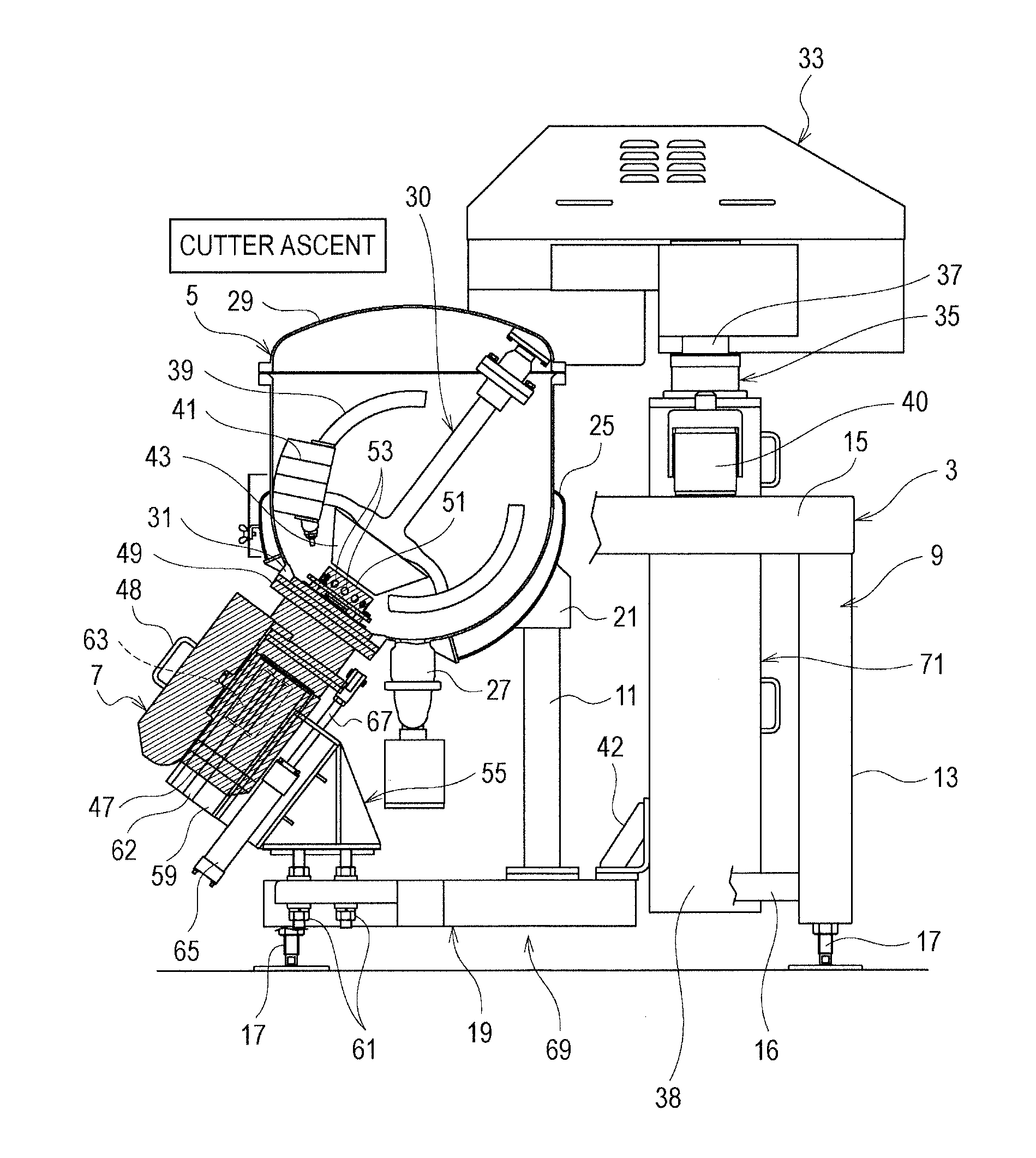
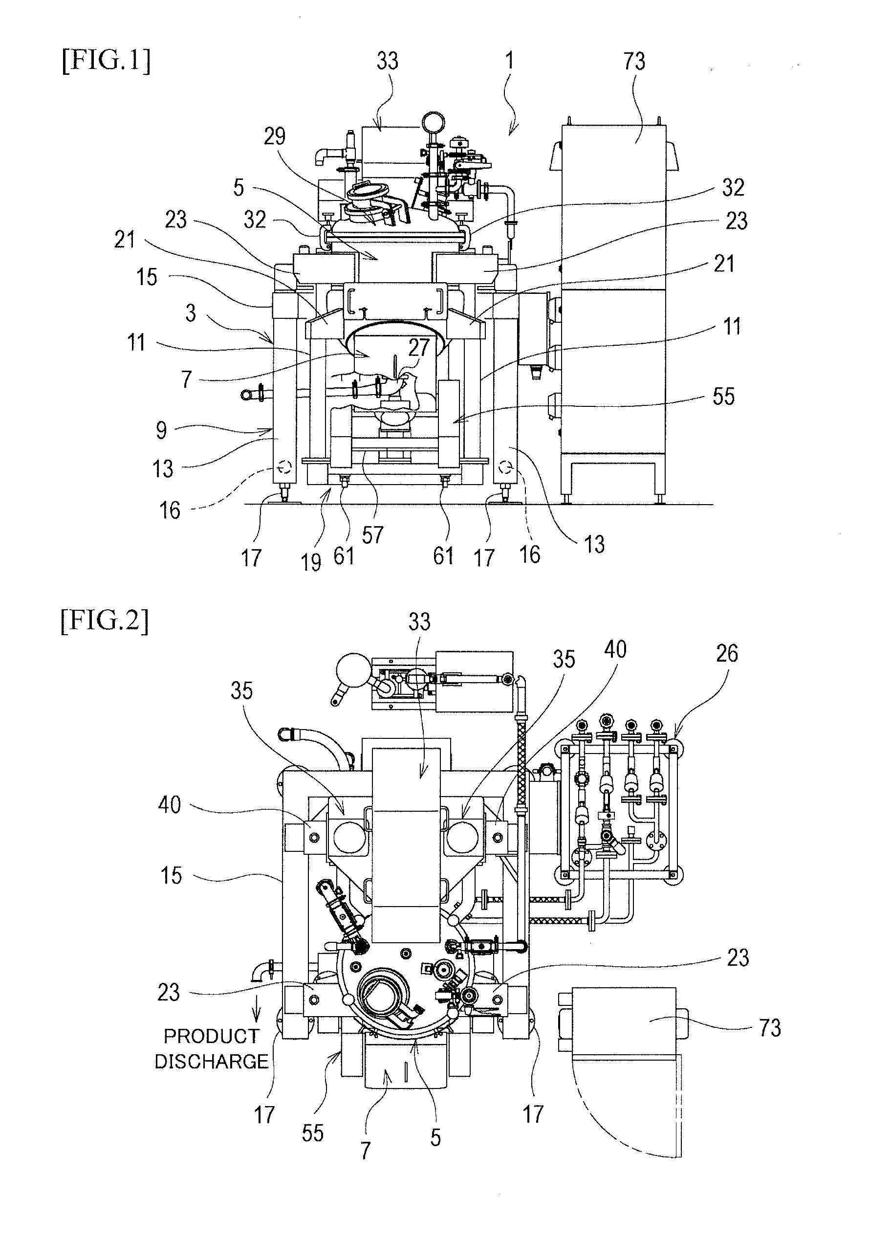
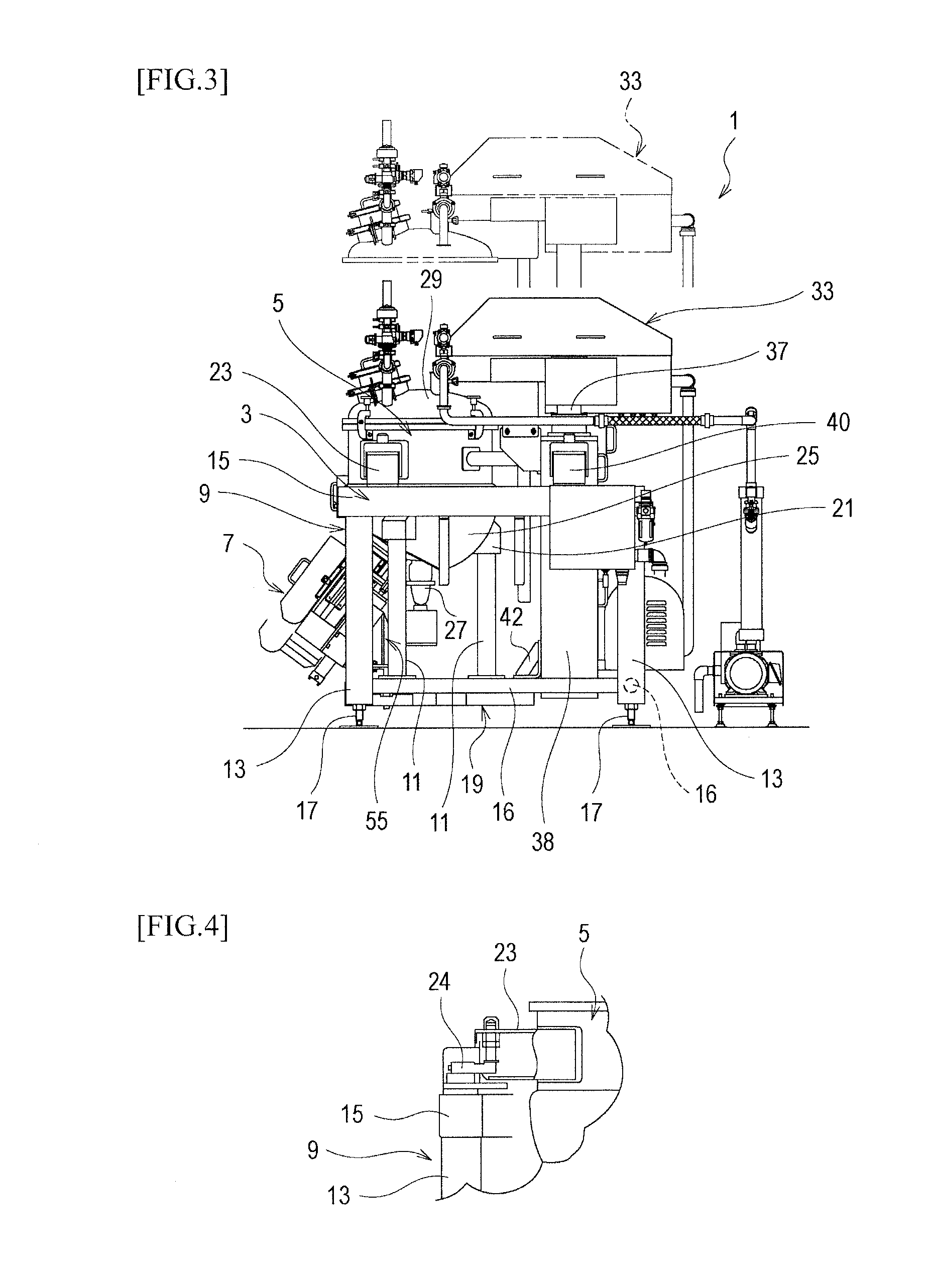
[0019]The object capable of accurately performing a weight measurement during a rotation operation while suppressing increase in reinforcement structures required for support of a stirring container and suppressing increase in weight is accomplished by that a device frame 3 is provided with legs 17, a heating kettle 5 is provided with a reinforcement base 19 attached on the bottom side, a motor bed 55 is provided to support a cutter / motor unit 7 to the reinforcement base 19 or the device frame 3, load ceils 24 . . . are provided capable of indirectly measuring a change in weight of a stirring substance in the heating kettle 5 during a rotation operation of the cutter / motor unit 7, and closed reinforced structures 69, 71 are configured to include the heating kettle 5, the cutter / motor unit 7, the reinforcement base, and the supporting stand as reinforcing members.

[0020]FIG. 1 is a front view of a heating-and-stirring cooking device, FIG. 2 is a plan view of the heating-and-stirring c...


PUM


Abstract

Provided is a stirring device that allows a weight measurement during a rotation operation to be accurately performed while suppressing increase in reinforcement structures required for support of a stirring container and suppressing increase in weight, A device frame is provided with legs, a heating kettle is provided with a reinforcement base attached on the bottom side, a motor bed is provided to support a cutter / motor unit to the reinforcement base or the device frame, load cells are provided to indirectly measure a change in weight of a stirring substance in the heating kettle during a rotation operation of the cutter / motor unit, and closed reinforced structures are configured to include the heating kettle, the cutter / motor unit, the reinforcement base, and the supporting stand as reinforcing members.

Description

FIELD OF THE INVENTION[0001]The present invention relates to a stirring device available for producing food such as mayonnaise and dressing, cosmetics, drugs, and chemicals etc, to be emulsified,BACKGROUND OF THE INVENTION[0002]As this type of a conventional stirring device, for example, there is one disclosed in Patent document 1.[0003]This stirring device is provided with a cutter / motor unit attached to one side of a bottom part of a heating kettle as a stirring container. The cutter / motor, in which a cutter part and a motor part are coaxially and integrally formed and are linked with each other, is attached to the bottom part of the heating kettle, The cutter part faces inside the heating kettle.[0004]Into the heating kettle, supporting rods attached to a stirring shaft is inserted from the top. To the supporting rods, a plurality of scraping blades are attached.[0005]Therefore, with the cutter / motor unit, a stirring substance such as ingredient is further efficiently stirred and...

Claims


Application Information

Patent Timeline
IPC IPC(8): B01F7/00A47J36/16A47J43/04B01F15/00B01F15/06A23L5/10A23L27/60
CPCB01F7/0035B01F15/00538B01F15/00831B01F2015/062B01F15/06A47J43/04A47J36/165B01F15/00194A47J27/004A23L5/10A23L27/60B01F27/07261B01F27/091B01F27/61B01F27/806B01F33/833B01F33/83611B01F35/2117B01F35/92B01F2035/99B01F27/1131B01F35/51B01F35/90B01F35/3204
Inventor KAJIWARA, HIDEHIROISHII, NORIKAZUSUZUKI, MASATOSHI
Owner KAJIWARA
Learn More