Hypersonic laminar flow control

a technology of laminar flow and hypersonic, applied in the direction of air flow influencers, mechanical devices, transportation and packaging, etc., can solve the problems of reducing the total drag of the vehicle, not using laminar flow control methods, and reducing the drag at the base of the vehicl

Active Publication Date: 2015-11-26
RGT UNIV OF CALIFORNIA
View PDF17 Cites 30 Cited by
  • Summary
  • Abstract
  • Description
  • Claims
  • Application Information

AI Technical Summary

Problems solved by technology

Strictly speaking, this method is not for laminar flow control.
Although the roughness leads to drag increase in the roughened area of the forebody, it significantly decreases drag at the base of the vehicle.
As a result, total drag upon the vehicle decreases.
However, it is difficult to use such a complex system for a hypersonic boundary layer.
However, porous coating generally has no effect on the mean flow and the instability of the second mode, which make it difficult to achieve the efficient stabilization of hypersonic flows.
The manufacturing of porous coating and the attachment of porous coating to body surface are not so convenient.
It is sometimes difficult for a porous coating to achieve efficient stabilization of hypersonic flows.
In addition, the stabilization of porous coating depends on material properties of the coating and covering the vehicle surface with porous coatings may affect the strength and aerodynamic performance of the vehicle.
Finally, it may be very difficult to put several porous coatings on a vehicle surface at different locations and removal of porous coatings from vehicle surface is difficult as well.
The method is essential for the laminar control method in U.S. Pat. No. 5,884,871, but it is not a method to control laminar flow.
Although the method is valid for subsonic flows, it is difficult to be applied to hypersonic flows.
The method also requires a complicated system for acoustic generators and its control.
The stabilization effect of surface roughness has been mentioned in a couple of journal papers by experimentalists as failures of studies of how to trip transition efficiently when the height of roughness is lower than the local boundary-layer thickness.
A review of the foregoing patents and applications shows there are quite limited methods for the control of hypersonic laminar flow of the boundary layer.
However, the described techniques are complex and difficult to implement.

Method used


Image

  • Hypersonic laminar flow control
  • Hypersonic laminar flow control
  • Hypersonic laminar flow control

Examples


Embodiment Construction

[0043]1. Overview

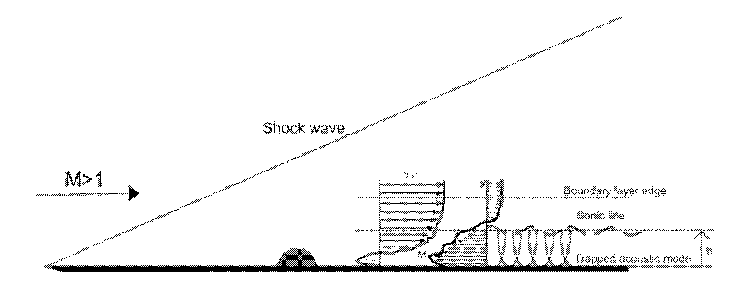
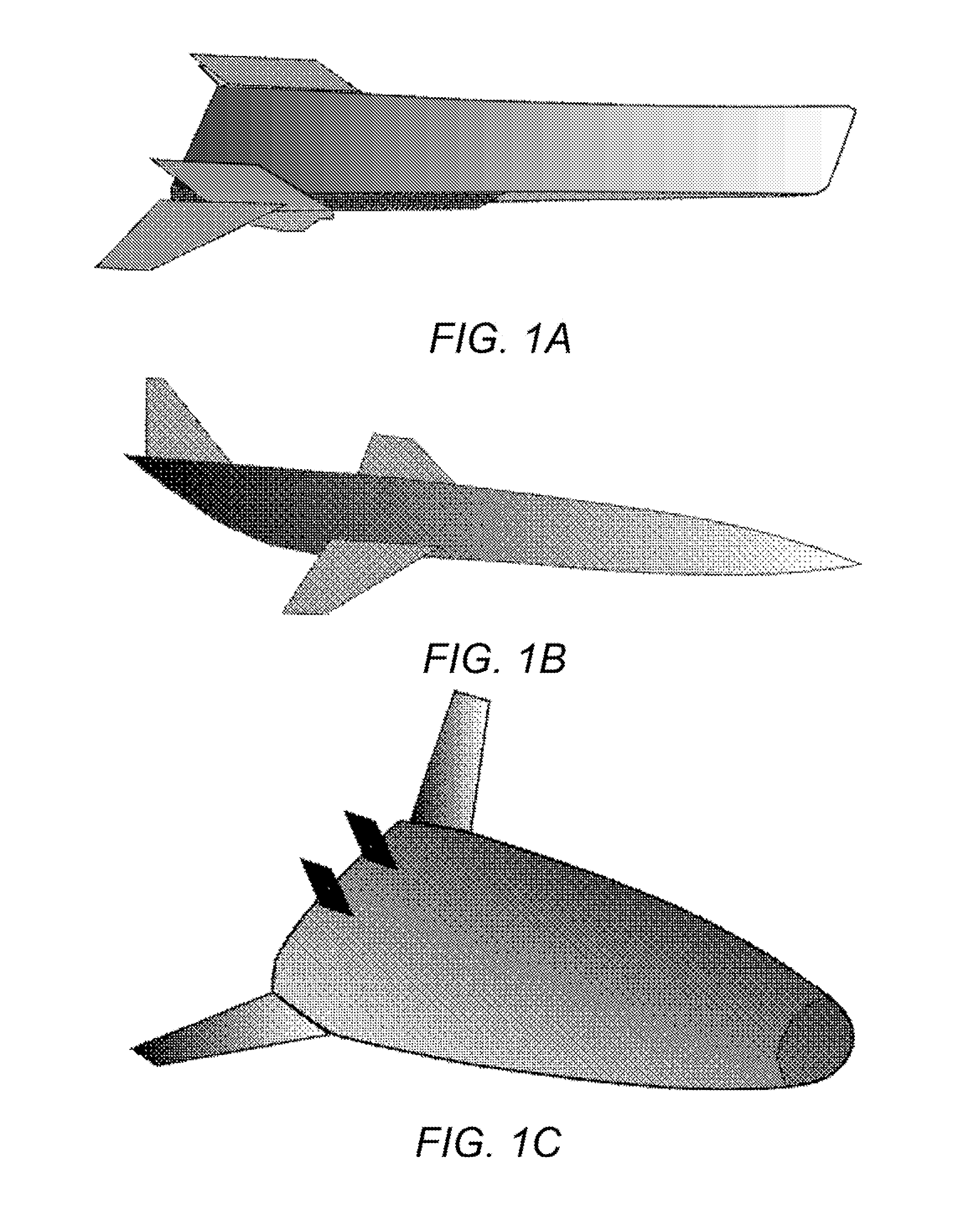
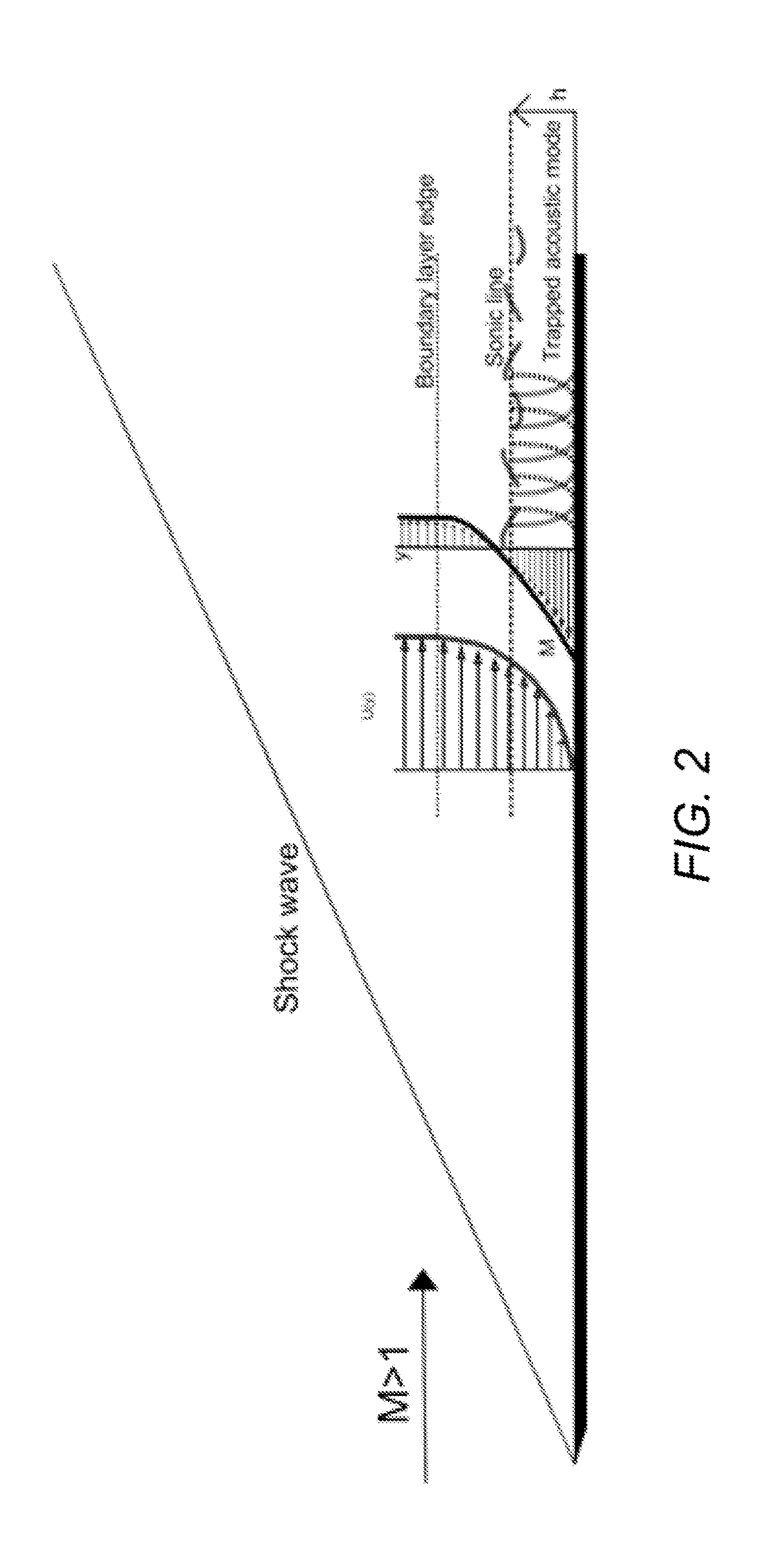
[0044]The present application discloses a novel passive control strategy for laminar flows over air transportation vehicles and space reentry vehicles flying at high supersonic and hypersonic speeds by using surface roughness to maintain laminar flow by delaying the laminar-turbulent transition. (As used in the present application, applicable flow speed may simply be referenced as “supersonic” which will be understood to include hypersonic speeds, i.e. above Mach 5.) The strategy is focused on flow transition caused by the so called second mode instability. It can be applied to supersonic and hypersonic airplanes and space reentry vehicles. The technique of using such surface roughness elements to stabilize hypersonic boundary layers has not been previously described.

[0045]The control of laminar flow can be achieved by applying an array of surface roughness elements in the region before the laminar-turbulent transition. The control of laminar flows is achieved by ap...


PUM


Abstract

A novel passive control technique for laminar flow over air transportation vehicles and space reentry vehicles flying at high supersonic and hypersonic speeds is disclosed. The control of laminar flow can be achieved by applying an array of surface roughness elements in the region before the laminar-turbulent transition. For example, an array of two-dimensional rings, stripes, or closely packed three-dimensional isolated roughness elements may be used to stabilize the instability waves and delay transition. The roughness elements may have a height between 40% and 60% of the local boundary-layer thickness. The exact location, height, and spacing of surface roughness elements may be determined by a numerical simulation strategy based on the most unstable second mode, e.g. using known eN transition prediction method, experimental measurement, or any other suitable technique.

Description

CROSS-REFERENCE TO RELATED APPLICATIONS[0001]This application claims the benefit of the following co-pending and commonly-assigned U.S. provisional patent application:[0002]U.S. Provisional Patent Application Ser. No. 61 / 728,214, filed Nov. 19, 2012, which is incorporated by reference herein.STATEMENT OF GOVERNMENT RIGHTS[0003]This invention was made with Government support under Grant No. FA9550-09-1-0341, awarded by the United States Air Force, Air Force Office of Scientific Research. The Government has certain rights in this invention.BACKGROUND OF THE INVENTION[0004]1. Field of the Invention[0005]The present invention relates to surface design of vehicles, and particularly to the surface design of hypersonic vehicles.[0006]2. Description of the Related Art[0007]The transition of boundary-layer flows over hypersonic vehicle surfaces significantly affects the performance of hypersonic transportation vehicles and re-entry vehicles and the design of their thermal protection systems....

Claims


Application Information

Patent Timeline
Patent Type & Authority Applications(United States)
IPC IPC(8): B64C21/10F15D1/08
CPCB64C21/10B64C2230/26F15D1/08B64C30/00Y02T50/10
Inventor ZHONG, XIAOLINFONG, KAHEI DANNYWANG, XIAOWEN
Owner RGT UNIV OF CALIFORNIA
Why Eureka
Try Eureka