Adjustable spherical joint member

a spherical joint and adjustment technology, applied in the direction of connection, rigid shaft coupling, basic electric elements, etc., can solve the problem of imprecise positioning of the joint, and achieve the effect of stable and secure connection

Active Publication Date: 2015-11-26
TECRES SPA
View PDF17 Cites 12 Cited by
  • Summary
  • Abstract
  • Description
  • Claims
  • Application Information

AI Technical Summary

Benefits of technology

[0017]A further object of the present invention is to prove an adjustable ball joint, which is suitable for ensuring a connection between a first and a second component in adjustable positions, whose configuration is simple, and comprises a small number of components.
[0018]A further object of the present invention is to provide a ball joint of the adjustable type that ensures a stable and secure connection between a first and a second component.
[0019]Another object of the present invention is to provide a ball joint of the adjustable type that comprises blocking / releasing means the actuation thereof being simple and easy.

Problems solved by technology

One drawback of such blocking means is the requirement of making seats, wherein the ball portion of the joint is to be housed, that are extremely precise so as to avoid undesired jamming during the movement of the joint itself that would, otherwise, cause the joint itself to be positioned imprecisely.

Method used


Image

  • Adjustable spherical joint member
  • Adjustable spherical joint member
  • Adjustable spherical joint member

Examples


first embodiment

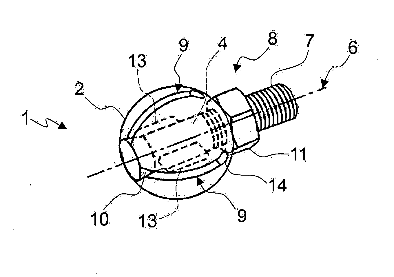
[0077]The configuration of the spherical element 102 is however different with respect to that of the More particularly, the spherical element comprises a substantially cylindrical central portion 102′, between two substantially spherical cap shaped portions 102″.

[0078]The spherical element 102 is sized so that the circular base of each substantially spherical cap shaped portion 102″ matches a respective base of the substantially cylindrical portion 102′. The spherical element 102 can be obtained either enbloc, for example through milling of a portion of the outer surface of the spherical element 102, or through the assembly, in a way known to the skilled person, of many separate components. The substantially cylindrical central portion 102′ has, at its circular cross-section, a radius r shorter than the curvature radius R of each spherical cap 102″, so that the spherical element 102 has reduced overall dimensions in a plane parallel to the bases of such a cylindrical central porti...

second embodiment

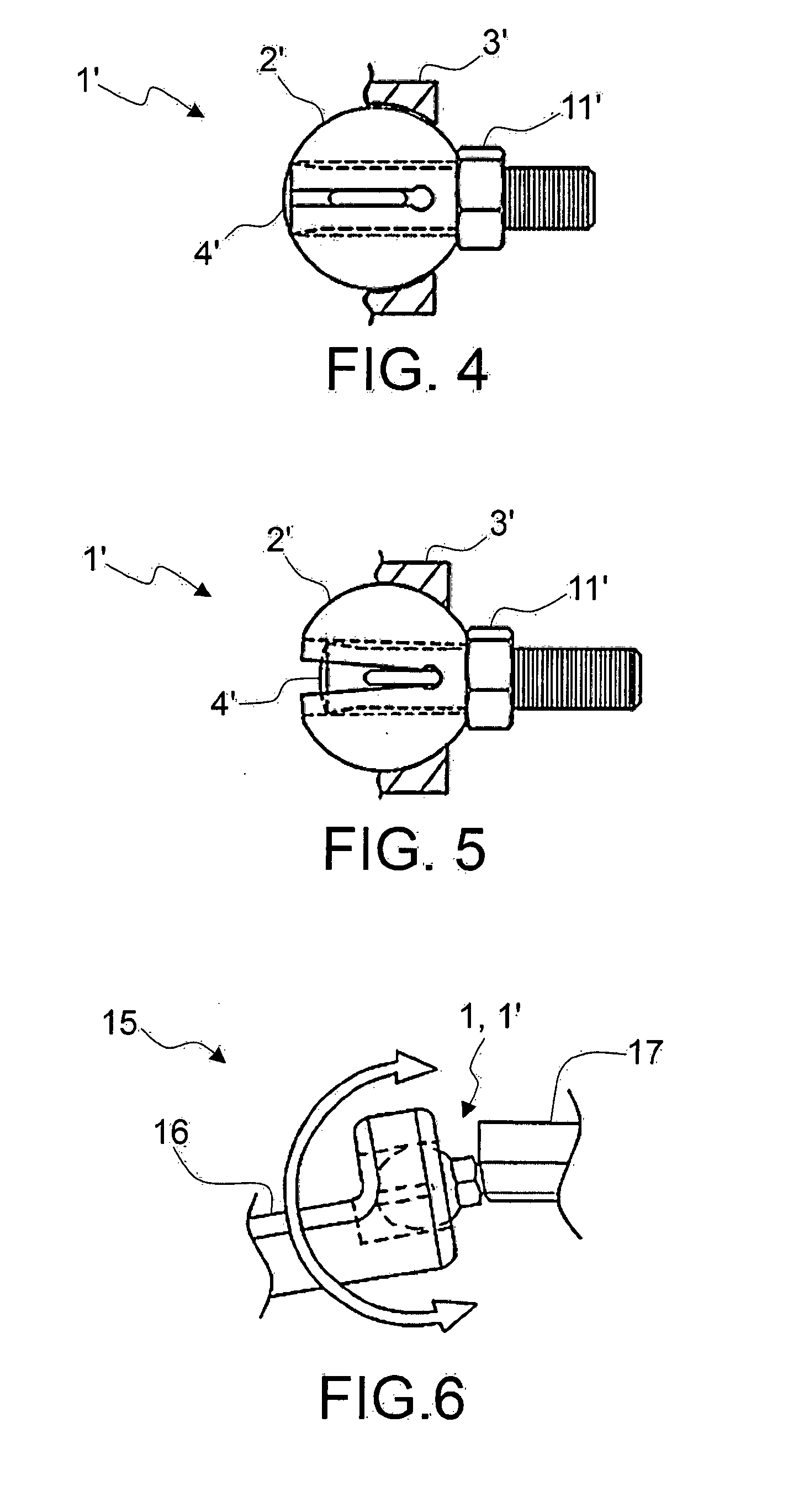
[0098]In order to connect one first and one second component to one another through the ball joint 100 according to the present invention, the spherical element 102 is inserted in the respective seat 103 obtained in a first component and the ball joint 100 is connected, through insert 104, to the second component.

[0099]An insert of this type is designed to be housed in a respective hollow seat 103 configured substantially like a spherical cap and, more particularly, having a radius of curvature that is slightly longer than the curvature radius R of the substantially cap-shaped portions 102″ of insert 100, and defining an inlet mouth 103′ with a substantially circular configuration with a radius that is slightly longer than the radius r of the circular section of the substantially cylindrical central portion 102′, but shorter than the radius of curvature R of the substantially cap-shaped portions 102″. The substantially spherical cap-shaped housing seat 103 has a volume that is at le...

third embodiment

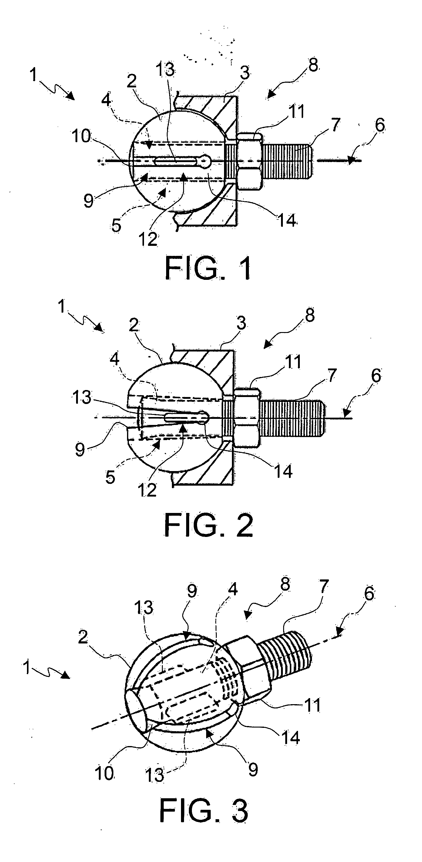
[0105]With reference now to FIGS. 10 to 13, it can be noted how a ball joint according to the present invention is indicated with reference numeral 200 and comprises a substantially spherical element 202, designed in use to be positioned inside a respective hollow housing seat 203 obtained in a first component, and an insert 204, connected to the spherical element 202, as will be better described below, and associable, in use, with a second component.

[0106]More particularly, the spherical element 202 comprises a substantially cylindrical central portion 202′, between two substantially spherical cap shaped portions 202″. The spherical element 202 is dimensioned so that the circular base of each substantially spherical cap shaped portion 202″ matches a respective base of the substantially cylindrical portion 202′. The spherical element 202 can be obtained either enbloc, for example through milling of a portion of the outer surface of the spherical element itself, or it can be obtained...


PUM


Abstract

The present invention relates to a ball joint, associable with a first and a second component for their connection in an adjustable position, including a spherical element, at least partially housable in a hollow housing seat of said first component, an insert, connected to such a spherical element and removably associable with such a second component, wherein the spherical element includes a substantially cylindrical central portion, interposed between two substantially spherical cap shaped portions arranged with respect to one another so that each circular base of each substantially spherical cap shaped portion matches a respective base of such a substantially cylindrical portion.

Description

TECHNICAL FIELD OF THE INVENTION [0001]The present invention refers to a ball joint of the adjustable type, and in particular to a ball joint for stable connection of a first and second component in adjustable positions.STATE OF THE ART [0002]The use of a ball joint for the articulated connection between at least two components is known in various sectors such as, for example, the automobile industry, medical sector, etcetera.[0003]Known types of ball joints comprise a housing seat that is obtained in or associated with a first component, and a spherical element that is equipped with a pin, which is associated with a second component.[0004]By introducing the spherical element in the respective seat, for example spherical, the connection between the first component and the second component is obtained.[0005]With reference to the automobile industry, a typical application of the ball joints is provided for the connection between the suspensions arms, thereby obtaining a rotatable mova...

Claims


Application Information

Patent Timeline
Patent Type & Authority Applications(United States)
IPC IPC(8): F16C11/06
CPCY10T403/32631F16C11/06F16C11/0604F16C11/106
Inventor FACCIOLI, GIOVANNISOFFIATTI, RENZO
Owner TECRES SPA
Why Eureka
Try Eureka