
Valve controller

Inactive Publication Date: 2015-11-26
TLX TECH
View PDF0 Cites 7 Cited by
  • Summary
  • Abstract
  • Description
  • Claims
  • Application Information

AI Technical Summary

Benefits of technology

The present invention is a valve controller that is durable, long-lasting, and requires minimal maintenance. The apparatus is designed with a moveable aperture and a circular permanent magnet that is independent of the ferrous core and armature pin of the valve controller. The armature is configured to move further than the armature pin to close the valve, and the design provides high shock load resistance to closing the valve. The technical effects of the invention are its durability, long-lasting, and low-maintenance requirements. The invention is also of inexpensive construction, which increases its market appeal.

Problems solved by technology

In such configurations, there is thus an increased energy requirement to unlatch the device.

Method used


Image

  • Valve controller
  • Valve controller
  • Valve controller

Examples


Embodiment Construction

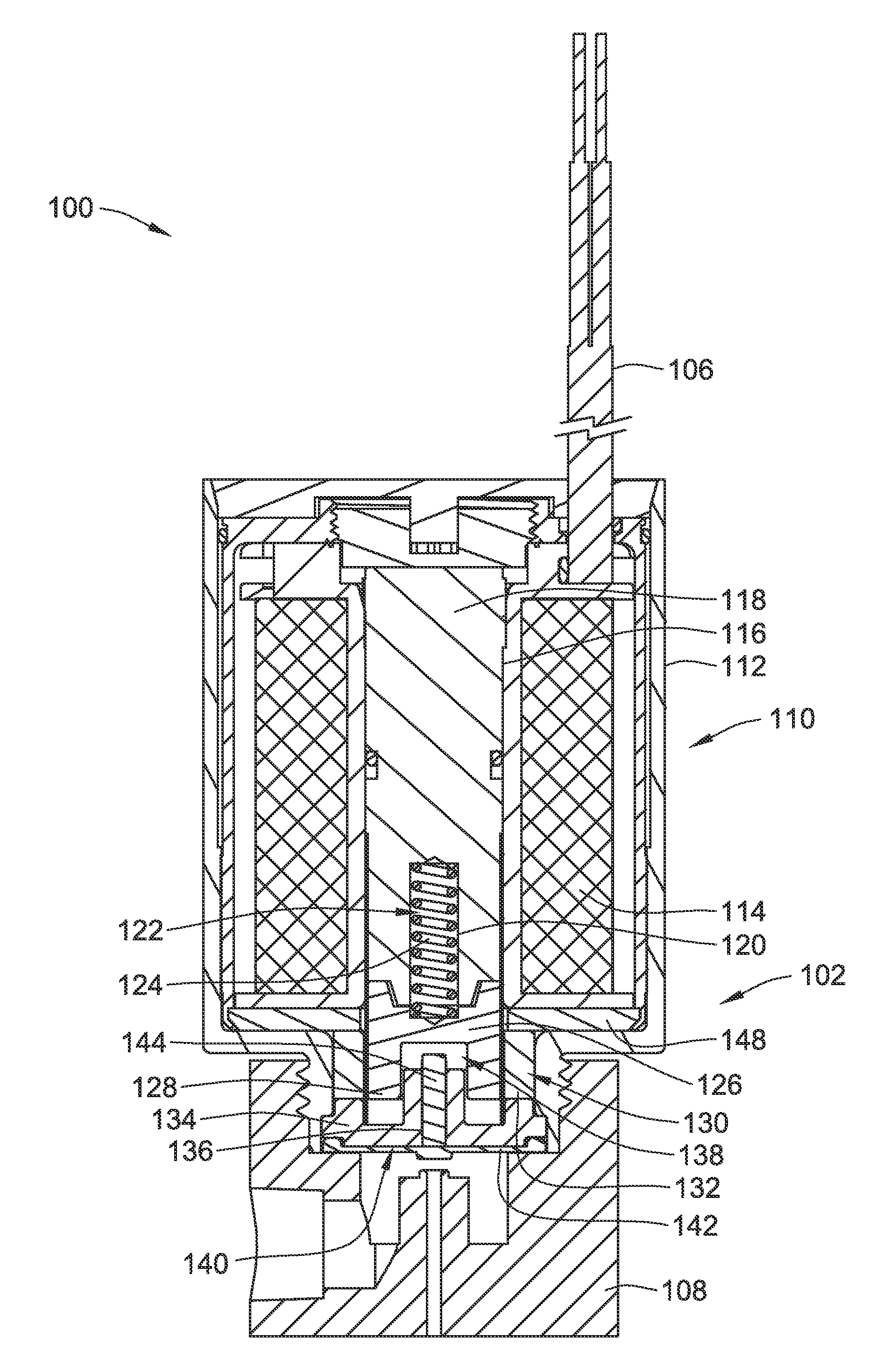
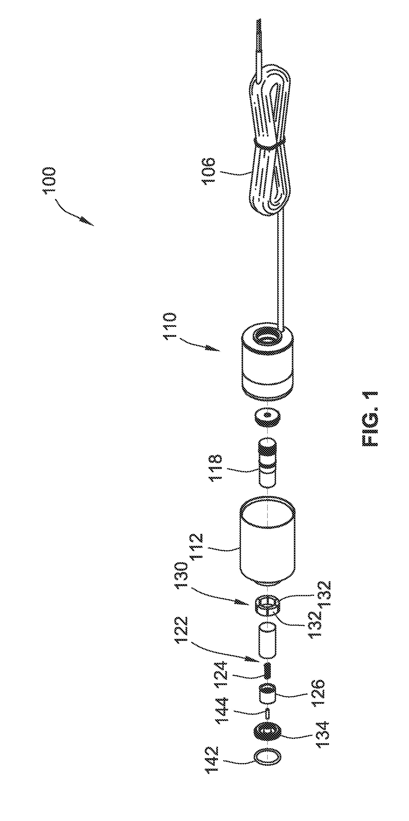
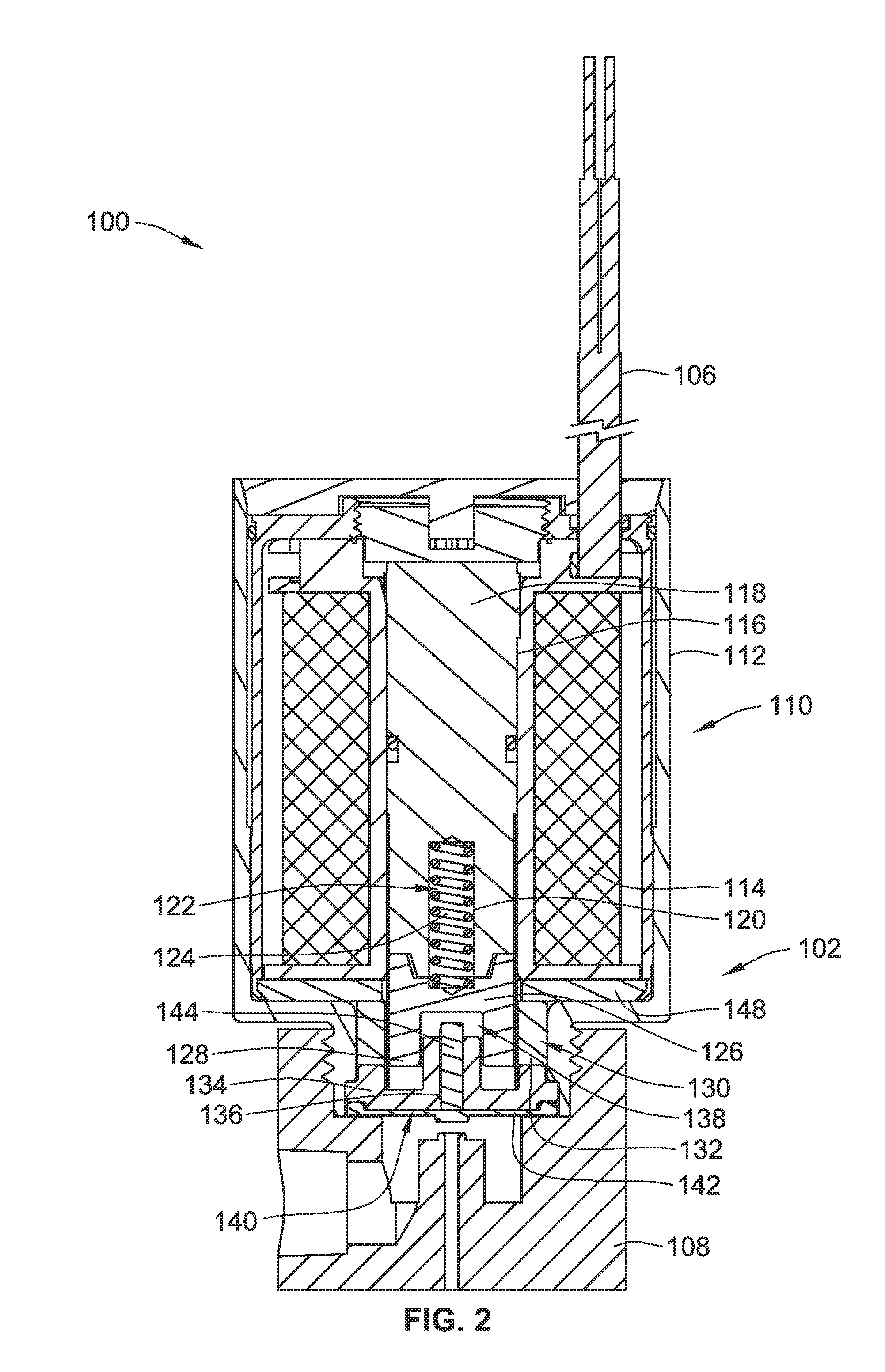
[0029]An exemplary embodiment of a valve controller 100 is illustrated in FIGS. 1-3. The valve controller is also referred to as a latching diaphragm pilot valve. The valve controller 100 is configured to close a valve 108 coupled to the valve controller.

[0030]The valve controller 100 includes a solenoid housing 112 with an electric coil winding 114 disposed in the housing with the coil winding 114 defining a central opening 116. A ferrous core 118 is disposed in the central opening 116, the ferrous core defining a recess 120. The ferrous core is composed of a magnetic metal which is magnetically affected by the electric coil winding 114.

[0031]A biasing device 122, for example a coil spring 124, is configured to store a biasing force and is disposed in the recess 120. A moving armature 126 is aligned with the ferrous core 118 and is in operative contact with the biasing device 122. The moving armature 126 is configured to receive the biasing device 122 and is also configured to rece...


PUM


Abstract

A valve controller is provided. The valve controller includes an armature formed by a moving armature and an armature pin. The moving armature movable from a latched position in which it is decoupled from the armature pin and in contact with a core, to an unlatched position where it is decoupled from the core and in contact with the armature pin.

Description

CROSS-REFERENCE TO RELATED PATENT APPLICATIONS[0001]This patent application claims the benefit of U.S. Provisional Patent Application No. 62 / 001,440, filed May 21, 2014, the entire teachings and disclosure of which are incorporated herein by reference thereto.FIELD OF THE INVENTION[0002]The present invention relates generally to solenoids, and more particularly to a valve controller including a solenoid having an armature held in place by a magnetic latch independent of pressure without drawing any current in the solenoid.BACKGROUND OF THE INVENTION[0003]Magnetically latching solenoids are generally recognized as providing a low energy consumption alternative to constant current solenoid devices. In such constant current solenoid devices, a constant electrical current is required to be supplied to a winding to generate enough force to hold the armature of the solenoid in a desired position. When this current is removed, the armature is then returned to its default state, typically b...

Claims


Application Information

Patent Timeline
IPC IPC(8): F16K31/08F16K31/06
CPCF16K31/082F16K31/0675F16K31/0672H01F7/1615F16K31/06
Inventor MILLER, JUSTINROGALA, JEFF
Owner TLX TECH
Learn More