
Automated testing of an application system

an application system and automatic testing technology, applied in the field of automatic testing of applications systems, can solve the problems of time-consuming and expensive process, maintenance of these tests is also a very costly process of executing test cases, and the setup of these traditional approaches occurs

Active Publication Date: 2015-11-26
CGI TECH & SOLUTIONS
View PDF11 Cites 187 Cited by
  • Summary
  • Abstract
  • Description
  • Claims
  • Application Information

AI Technical Summary

Benefits of technology

The patent text describes a method for automatically testing a graphical user interface (GUI) application system by identifying text elements and user input objects on the GUI page, and retrieving associated test parameter values from a database. The test parameter values are then provided to the user input objects for testing. The method can help to automate the testing process and improve efficiency. The technical effects of the patent text include reducing the time and effort required for testing, and improving the accuracy of testing results.

Problems solved by technology

Traditional automation approaches for testing software systems require a well-trained professional test designer to undertake a very time consuming and expensive process to configure the automated testing software to perform a test of the software system.
The setup for these traditional approaches occurs prior to any test execution and is very costly.
The maintenance of these tests is also a very costly process of executing test cases, encountering failures, analyzing the failures, making coding or test case updates, and executing the test again to reach a positive run status.
However, such scripting tools were blind of the context of the GUI and therefore prone to error and failure if any minor change was made to the GUI or to the testing environment.
However, such methods rely on having access to the code of the application under test, such as source code or data definitions, and therefore have limited applicability.
Further, such methods rely on programmers to review the code to create test cases, and the methods are therefore very costly and slow to implement.
Further, maintenance is difficult as programmers are also needed to make adjustments to tests any time the original code is modified or updated.
Unfortunately, these frameworks run on top of more complex programmer tools, and thus still require programmers and experts to setup the projects, often taking two to four weeks or more for each application to get it into a state ready for automation.
Furthermore, most applications require extensive workarounds with the common market leading automation tools to work with the complex applications created today.
Further, the automation of a test case using established testing systems requires a great deal of effort for automation programmers to setup and manage every automation project.
Because of the customizations needed in the coding centric automation tool to recognize each new application, and because of the need for skilled coding resources to do this work, test automation using established systems is only viable for regression testing or only achieves positive return on investment (ROI) after four or more releases.
As an example, in a table with Edit buttons on the right side which have a slight gradient in color from one row to the next, a simple pattern matching may fail because the Edit buttons are not identical images even though they are logically repeated objects.
The prior tools' approach results in much higher setup costs and longer timeframes for setup of such other tools in comparison to the automation tool detailed herein.
The prior tools often require experts who are programmers which are expensive and difficult to find in the testing market, and the maintenance of the prior tools is also very expensive and must be performed by these coders.
Some Interfaces are dynamic in size and thus will not have this caching enabled.

Method used


Image

  • Automated testing of an application system
  • Automated testing of an application system
  • Automated testing of an application system

Examples


Embodiment Construction

[0028]In the following detailed description, numerous specific details are set forth by way of examples in order to provide a thorough understanding of the relevant teachings. However, it should be apparent to those skilled in the art that the present teachings may be practiced without such details. In other instances, well known methods, procedures, components, and / or circuitry have been described at a relatively high-level, without detail, in order to avoid unnecessarily obscuring aspects of the present teachings.

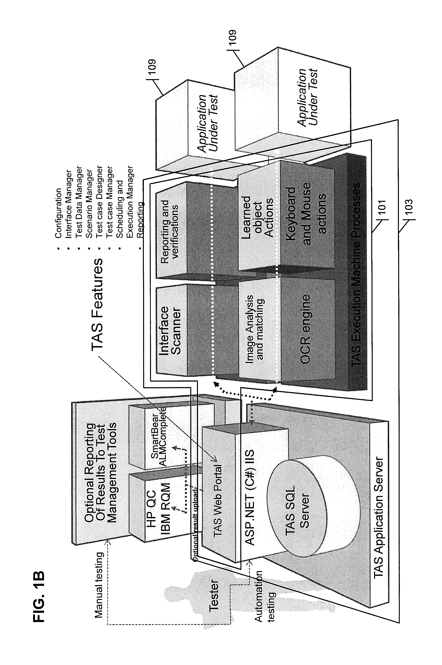
[0029]The various methods and systems disclosed herein relate to the automated testing of complex software systems. Systems and methods are provided which use optical character recognition (OCR), pattern matching, image matching, positional, and other visual and shape detection algorithms to learn a graphical user interface (GUI) of a software application with the intention of interacting with it repeatedly as a user would for the purpose of test automation.

[0030]The auto...


PUM


Abstract

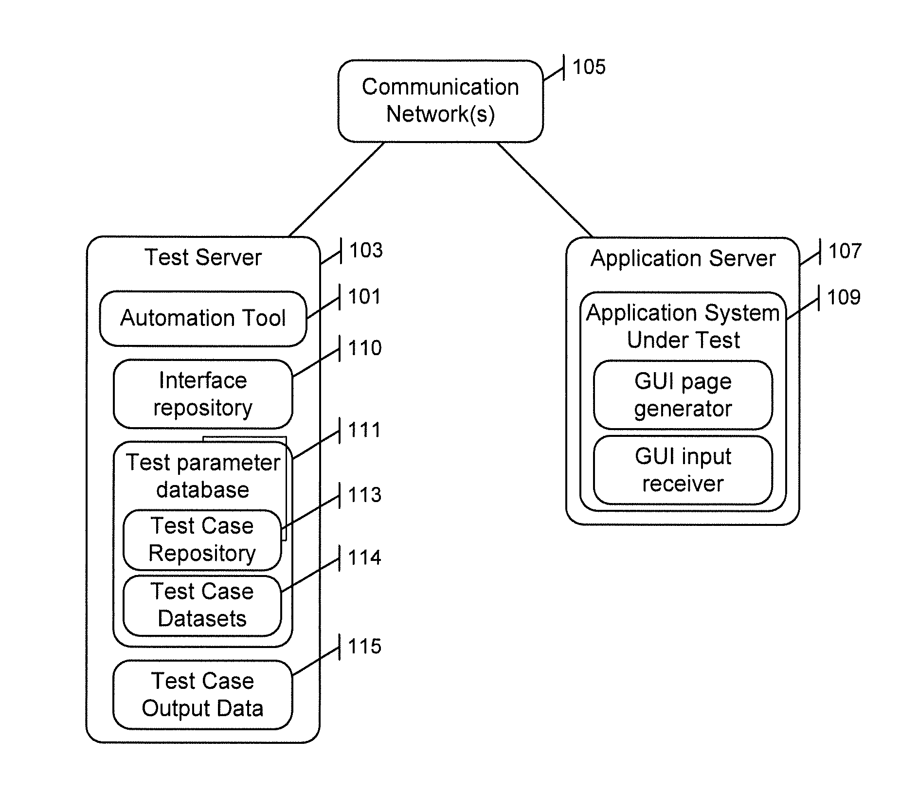
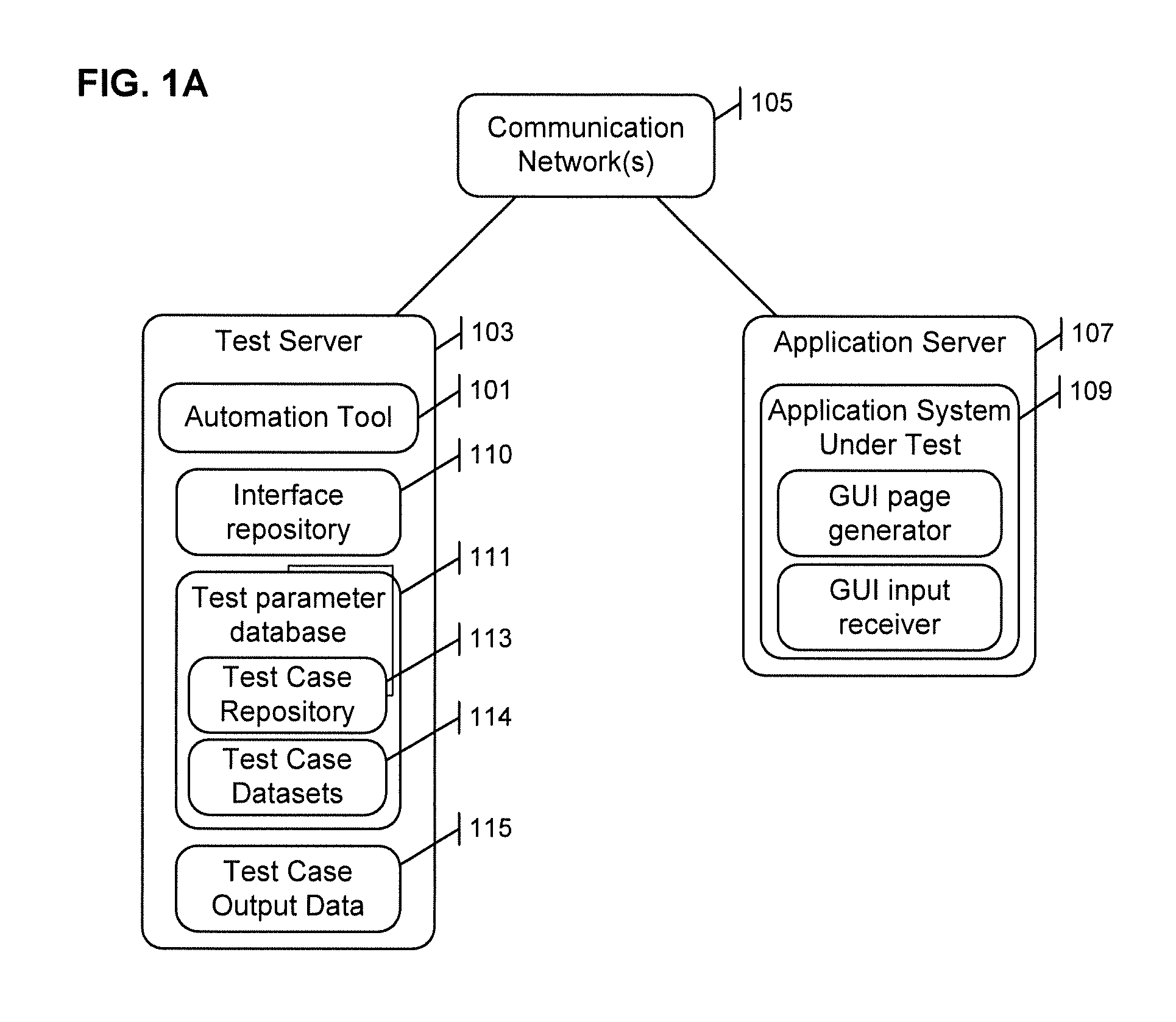
A system for automatically testing an application system graphical user interface (GUI) includes first and second application servers communicatively connected across a communication network. The second application server retrieves a GUI page provided by the first application server as part of the application system, and identifies text elements and user input objects in an image of the retrieved GUI page. Each user input object is then associated with a text element. Test parameter values are retrieved from a database storing test parameter data, and the application system is tested. In particular, for each user input object of the GUI page, a respective test parameter value is provided that is associated in the database with a same text element as is associated with the user input object. A response of the application system is then monitored.

Description

CROSS-REFERENCE TO RELATED APPLICATION[0001]This application claims the benefit of U.S. Provisional Patent Application No. 62 / 001,501, filed on May 21, 2014 in the United States Patent and Trademark Office, the disclosure of which is incorporated by reference herein in its entirety.TECHNICAL FIELD[0002]The present invention relates to a system and methods for automating the testing of an application system having one or more graphical user interfaces (GUIs) by automating interactions with the GUIs of the application system under test (AUT).BACKGROUND[0003]Traditional automation approaches for testing software systems require a well-trained professional test designer to undertake a very time consuming and expensive process to configure the automated testing software to perform a test of the software system. In particular, the test designer must generally be a programmer rather than a manual tester such as is commonly used to staff testing projects. The setup for these traditional app...

Claims


Application Information

Patent Timeline
Patent Type & Authority Applications(United States)
IPC IPC(8): G06F11/36G06F3/0484G06F3/0485G06F3/0482
CPCG06F11/3664G06F11/3676G06F3/0485G06F3/04842G06F3/0482G06F11/3672G06F11/3688G06F3/0484
Inventor LEE, CHRISTOPHER STEPHENMONARK, MICHAEL WILLIAMTHOMAS, KAREN LYNNMURPHREE, WESLEY EDSELBACA, KRISTIN LEIGH
Owner CGI TECH & SOLUTIONS
Learn More