Bistable electromagnetic actuator and surgical instrument

a technology of electromagnetic actuators and actuators, which is applied in the direction of dynamo-electric machines, dynamo-electric components, magnetic circuit shapes/forms/construction, etc., can solve the problem of strong increase of the switching force acting on the rotor, and achieve the effect of increasing the switching force, retaining force and/or switching for

Inactive Publication Date: 2015-11-26
OLYMPUS WINTER & IBE
View PDF5 Cites 6 Cited by
  • Summary
  • Abstract
  • Description
  • Claims
  • Application Information

AI Technical Summary

Benefits of technology

[0014]Advantageously, the rotor with the rotor pole shoes has an overall length in the axial direction which is greater than the outside distance of the stator pole shoes in the axial direction. A distance between the axial midplanes of the rotor pole shoes can be greater than the distance between the axial midplanes of the stator pole shoes. By means of such features, the balance between the retaining force and switching force can be favorably adjusted, and the switching force can be increased.
[0015]When the stator pole shoes have an equal axial width amongst each other, and / or the stator pole shoes have an equal axial width amongst each other, and / or the stator and / or the rotor(s) is or are formed symmetrically across a plane of symmetry, a symmetrical design of the actuator in the axial direction is realized so that the same retaining force predominates at the two end positions, or respectively at the first position and the second position, and equivalent switching force can be applied to change the position of the rotor in the actuator. In addition, only some of the cited geometric dimensions can be symmetrically realized. If the actuator is subject to a continuous load, for example from a side, it can be advantageous to interrupt the overall symmetry of the actuator in an axial direction and implement greater retaining force and / or switching force in one position than in another position.

Problems solved by technology

Furthermore, this strongly increases the switching force acting on the rotor.

Method used


Image

  • Bistable electromagnetic actuator and surgical instrument
  • Bistable electromagnetic actuator and surgical instrument
  • Bistable electromagnetic actuator and surgical instrument

Examples


Embodiment Construction

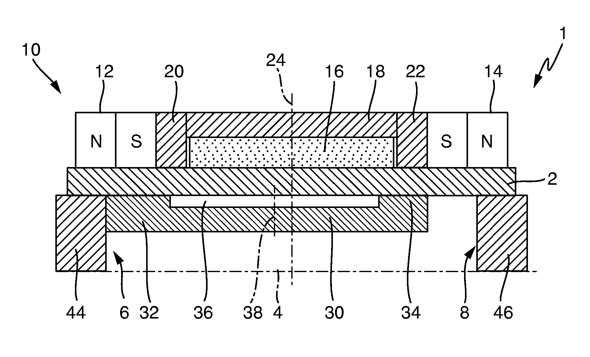
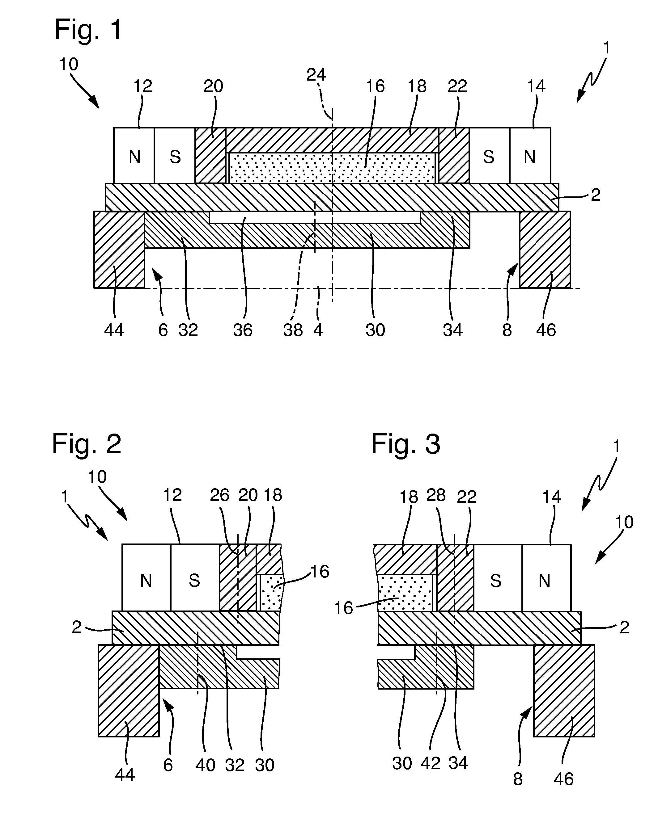
[0028]FIG. 1 shows a cross-section of a bistable electromagnetic actuator 1. The actuator is substantially rotationally symmetrical about the central axis 4, and only one-half of the actuator 1 is shown. Mirroring across the central axis 4 yields the entire section of the actuator 1.

[0029]In the following, the actuator 1 will be described as if it was located in a surgical instrument, i.e., in an endoscope with a distal end and proximal end. The distal direction is to the left in FIGS. 1 to 3, and the proximal direction is to the right.

[0030]A stator 10 is arranged radially outside of a tube 2 and has two ring magnets 12, 14 that are axially magnetized in opposite directions so that the south poles of the magnets lie opposite each other in FIG. 1. When integrated in an endoscope, the ring magnet 12 is a distal ring magnet, and the ring magnet 14 is a proximal ring magnet.

[0031]A cylindrical coil 16 is symmetrically arranged between the ring magnets 12 and 14, and a magnetic return e...


PUM


Abstract

A bistable electromagnetic actuator including: a tube; a stator arranged outside the tube, and a rotor mounted in the tube so as to be displaceable axially in the longitudinal direction, is the rotor being at least partially formed of one or more of a paramagnetic and ferromagnetic material, the rotor being reversibly moved between a first position and a second position by applying an electromagnetic field. Wherein the stator includes: two ring permanent magnets that are axially polarized in opposite directions, a coil for generating the electromagnetic field, and a magnetic return element having two stator pole shoes. Wherein, the magnetic return element with the stator pole shoes encloses the coil, one of the stator pole shoes is arranged on each of two sides of the coil between the coil and ring permanent magnets, the rotor has two rotor pole shoes, and an axial width of the stator pole shoes is smaller than an axial width of the rotor pole shoes.

Description

CROSS-REFERENCE TO RELATED APPLICATION[0001]The present application is a continuation of PCT / EP2014 / 000061 filed on Jan. 14, 2014, which is based upon and claims the benefit to DE 10 2013 202 019.8 filed on Feb. 7, 2013, the entire contents of each of which are incorporated herein by reference.BACKGROUND[0002]1. Field[0003]The present application relates to a bistable electromagnetic actuator, in particular for a surgical instrument, comprising a stator arranged outside a tube, and a rotor that is mounted in the tube so as to be displaceable axially in the longitudinal direction, which is of a paramagnetic and / or ferromagnetic material, at least in part, and which can be reversibly moved between a first position and a second position by applying an electromagnetic field, wherein the stator is provided with two ring permanent magnets that are axially polarized in opposite directions, a coil for generating the electromagnetic field, a magnetic return element having two stator pole sho...

Claims


Application Information

Patent Timeline
Patent Type & Authority Applications(United States)
IPC IPC(8): H02K33/16H02K1/17
CPCH02K1/17H02K33/16H01F7/1615H01F2007/083H01F2007/086H01F2007/1669
Inventor WIETERS, MARTIN
Owner OLYMPUS WINTER & IBE
Why Eureka
Try Eureka