Plough comprising a plurality of plough bodies attached to a plough bar

Inactive Publication Date: 2015-12-03
VON DER HEIDE HANS
View PDF11 Cites 4 Cited by
  • Summary
  • Abstract
  • Description
  • Claims
  • Application Information

AI Technical Summary

Benefits of technology

[0008]It is therefore an object of the present invention to create a plough of the aforementioned type, which obviates the drawbacks disclosed above and which, in parti

Problems solved by technology

In practice, however, when ploughs of the aforementioned type are in use, it has turned out that jams and congestions very easily occur between the plough bodies, with the result that the use of said ploughs is difficult or even impossible.
Because of the plough body with the so-called runner and the attachment for the moldboard, the free passage between two neighboring plough bodies is limited in part and, in extreme cases, up to half of its width, inevitably resulting in jams and congestions.
In like manner, the upright plough beam results in jams and congestions if the soil to be ploughed is covered with vegetation or loose residues.
In addition, the usual moldboard height which approximately corresponds to the cutting width of the

Method used


Image

  • Plough comprising a plurality of plough bodies attached to a plough bar
  • Plough comprising a plurality of plough bodies attached to a plough bar
  • Plough comprising a plurality of plough bodies attached to a plough bar

Examples


Example

[0048]In the following description of the figures, identical parts in the different figures will always be referred to with the same reference numbers, with the result that it is not necessary to illustrate all reference numbers for each figure of the drawing.

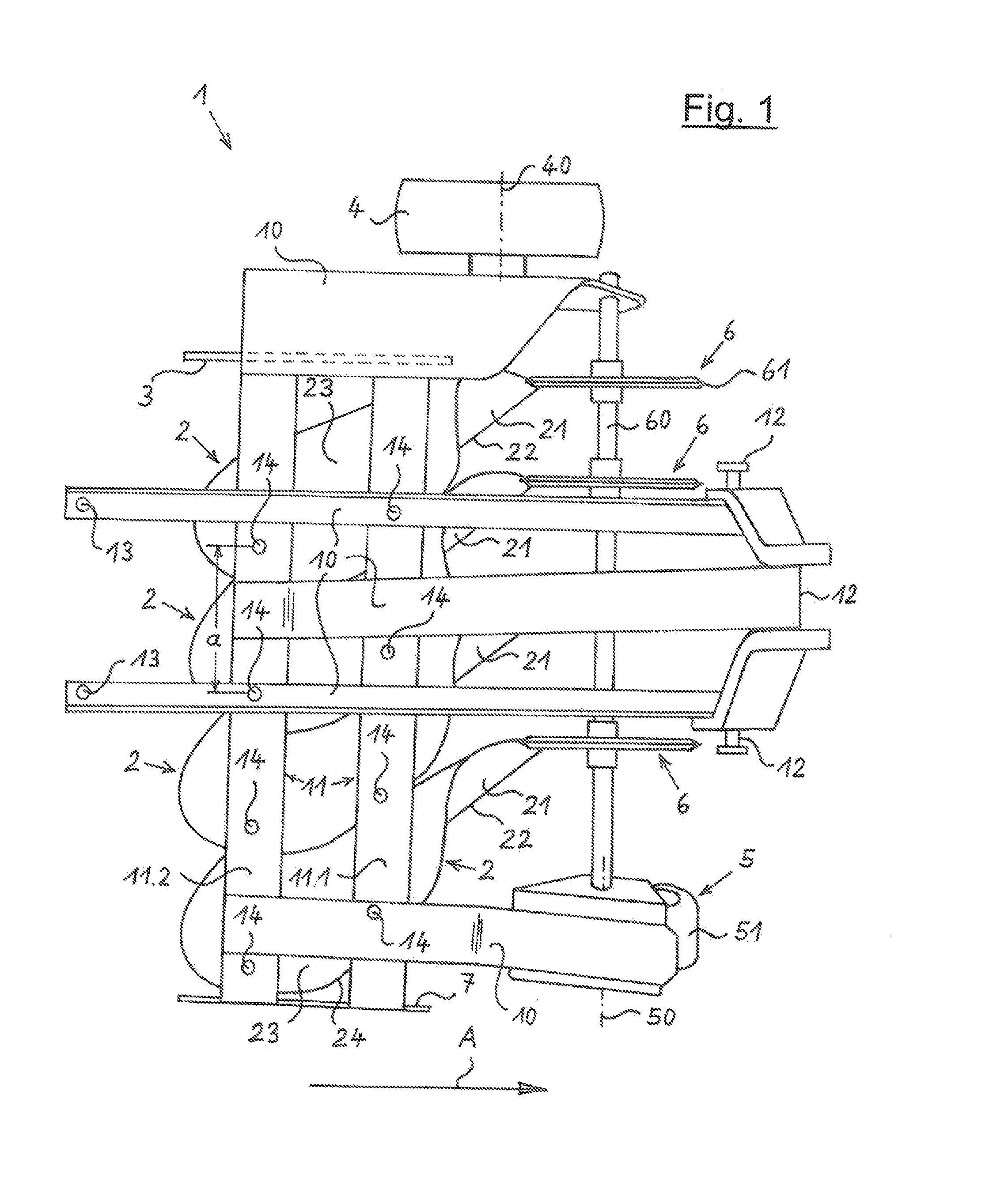
[0049]FIG. 1 of the drawing is a top view of a plough 1 wherein the front side of the plough 1 points to the right and, therefore, the working direction A of the plough 1 extends from left to right in the plane of the drawing.

[0050]The plough 1 has a plough frame 10 which, in the illustrated instance, comprises two horizontal longitudinal beams extending parallel to each other in working direction A, one diagonal beam which is arranged therebetween and extends from back to front in an inclined upward direction, and two front-end head pieces which are each connected, more preferably welded, to one of the longitudinal beams at their bottom and to the diagonal beam at their top. The head pieces carry standardized coupling elements...


PUM


Abstract

A plough comprising a plurality of plough bodies attached to a plough bar, wherein the plough bar is aligned at a right angle with respect to the working direction of the plough and wherein the plough bodies are arranged side-by-side on the plough bar for the purpose of ploughing a soil. In the disclosed plough, each plough body is a uniform component and has the shape of a tube that is bisected in longitudinal direction in a vertical plane and has slanted edges at its front and rear, wherein the longitudinal axes of the plough bodies are each aligned parallel to each other and at an angle with respect to the working direction of the plough.

Description

CROSS-REFERENCES TO RELATED APPLICATIONS[0001]This application claims the benefit of the German patent application No. 10 2014 107 515.3 filed on May 28, 2014, the entire disclosures of which are incorporated herein by way of reference.BACKGROUND OF THE INVENTION[0002]The present invention relates to a plough comprising a plurality of plough bodies attached to a plough bar, wherein the plough bar is aligned at a right angle with respect to the working direction of the plough and wherein the plough bodies are arranged side-by-side on the plough bar for the purpose of ploughing a soil.[0003]Document DE 18 13 113 A discloses a known plough in which a plurality of plough bodies that are known as such and have a share and a moldboard is arranged spaced apart side-by-side on a central plough bar and at a right angle with respect to the working direction, said plough bodies receiving horizontal cutting edges and scraper plates on the side facing away from the moldboard, said cutting edges ...

Claims


Application Information

Patent Timeline
IPC IPC(8): A01B15/02A01B3/40A01B59/06A01B73/02A01B49/02A01B63/10A01B63/00A01B15/18A01B59/00
CPCA01B15/02A01B15/18A01B3/40A01B59/066A01B73/02A01B49/027A01B63/10A01B63/008A01B59/00A01B15/08
Inventor VON DER HEIDE, HANS
Owner VON DER HEIDE HANS
Why Eureka
Try Eureka