Waste Compaction System For A Vehicle, Cabin Monument For A Vehicle Having Such A Waste Compaction System And Vehicle Having At Least One Waste Compaction System

a waste compaction system and vehicle technology, applied in the field of waste compaction systems for vehicles and cabin monuments for vehicles, can solve the problems of insufficient reliability of electromechanical waste compactors, low available space for waste collection and storage, and waste from passengers' meal packages and other used items, etc., to achieve the effect of increasing waste collection capacity and large capacity

Active Publication Date: 2015-12-03
AIRBUS OPERATIONS GMBH
View PDF6 Cites 12 Cited by
  • Summary
  • Abstract
  • Description
  • Claims
  • Application Information

AI Technical Summary

Benefits of technology

[0006]For the ease of use and an increased waste collection capacity it may be desired to provide a waste compaction system having movable trolleys with an as large capacity as possible and, at the same time, a least possible weight. Consequently, an aspect of the invention proposes an alternate waste compaction system for a vehicle with a movable trolley and a least possible weight.

Problems solved by technology

Waste may arise from meal packages and other used items from the passengers.
The most common approach for waste compaction systems in civil aircraft is based on electromechanical waste compactors, which are rather powerful but comprise a high weight due to the mechanical components such as motor, gears, supports and bearings.
Further, due to the weight of the compaction mechanism, the waste compactor is usually a fixed part of the galley and cannot be moved through the cabin.
The available space for waste collection and storage is low and the reliability of electromechanical waste compactors may be insufficient.

Method used


Image

  • Waste Compaction System For A Vehicle, Cabin Monument For A Vehicle Having Such A Waste Compaction System And Vehicle Having At Least One Waste Compaction System
  • Waste Compaction System For A Vehicle, Cabin Monument For A Vehicle Having Such A Waste Compaction System And Vehicle Having At Least One Waste Compaction System
  • Waste Compaction System For A Vehicle, Cabin Monument For A Vehicle Having Such A Waste Compaction System And Vehicle Having At Least One Waste Compaction System

Examples


Embodiment Construction

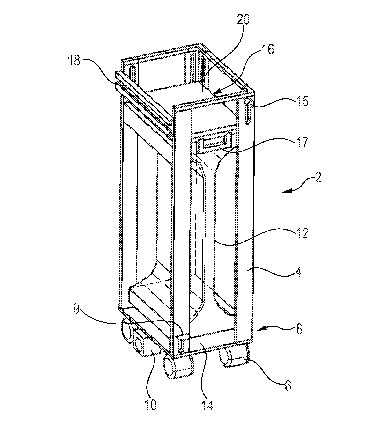
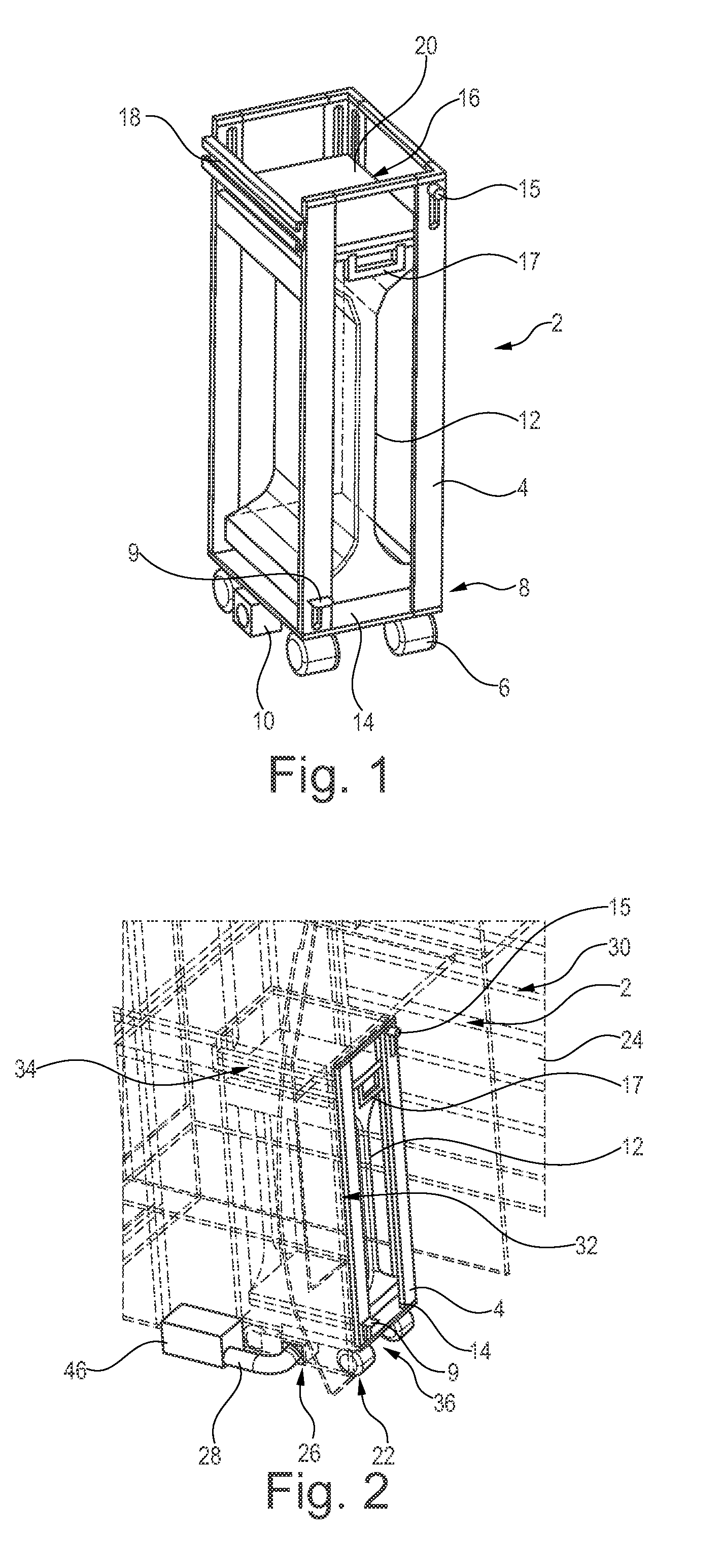
[0043]FIG. 1 shows a trolley 2 from a waste compaction system, the trolley comprising a housing 4, wheels 6 at a bottom region 8, a first suction port 10, a compaction sleeve 12 extending from a bottom plate 14 to an upper frame 16 and a guide rail 18 for aligning the trolley 2 in a predetermined spatial relationship to a counterpart of the rail 18. A locking lever 15 is located at a front side of the trolley 2 for locking or unlocking the upper frame 16. However, it may be worthwhile to consider a latching function when the upper frame 16 is pulled or moved into an uppermost position through handles 17 on opposite sides of the upper frame, such that the locking lever 15 is merely used for unlocking the upper frame 16. The trolley 2 is shown in a compaction position, which is explained in the following.

[0044]The compaction sleeve 12 is fixed to the bottom plate 14 in an airtight manner, e.g. through a tension belt surrounding the bottom plate 14 with a sealing material between the c...


PUM


Abstract

A waste compaction system for a vehicle includes a moveable trolley for storing waste, and a docking station integratable into a cabin monument for inserting the trolley. The trolley includes a housing having an opening for inserting waste, a vacuum waste compacting mechanism inside the housing and a first suction port accessible from outside the housing, the first suction port being couplable with the vacuum waste compacting mechanism. The docking station and the trolley are adapted to each other such that the trolley is engageable with the docking station, and wherein the docking station includes a second suction port couplable with a suction line in the vehicle and the first suction port. Resultantly, a lightweight and efficient waste compaction system is provided, which allows moving the trolley for collecting waste inside a cabin of the vehicle.

Description

FIELD OF THE INVENTION[0001]The invention relates to a waste compaction system for a vehicle, a cabin monument for a vehicle having such a waste compaction system and to a vehicle having at least one such waste compaction system.BACKGROUND OF THE INVENTION[0002]In large passenger vehicles, in particular aircraft for long haul flights, passenger capacities tend to be ever increasing, while at the same time the efficiency of the available space inside the cabin is more and more improved. For example, cabin monuments, such as galleys and lavatories, are increasingly space efficient and allow the integration of an optimized amount of passenger seats. Besides storing food and other items it is mandatory to provide sufficient space for collecting waste.[0003]Waste may arise from meal packages and other used items from the passengers. Simply collecting waste would lead to a plurality of bulky plastic bags, which need to be stored safely. To improve the waste collection and storage, it is k...

Claims


Application Information

Patent Timeline
Patent Type & Authority Applications(United States)
IPC IPC(8): B30B9/30B64D11/04B65F1/14
CPCB30B9/3039B30B9/305B64D11/04B65F1/1426B65F1/1473B65F1/1405B30B5/02B30B9/3057B30B9/3007
Inventor SCHLIWA, RALFSPILLE, MARC
Owner AIRBUS OPERATIONS GMBH
Why Eureka
Try Eureka