Liquid ejecting head and fabricating method for liquid ejecting head

a liquid ejecting head and fabrication method technology, applied in metal-working equipment, printing, writing implements, etc., can solve the problems of reducing the fabrication efficiency of the print head, and the inability to secure the contact pressure required for electric connection, so as to achieve high fabrication efficiency and high reliability of the electric connection

Active Publication Date: 2015-12-03
CANON KK
View PDF2 Cites 0 Cited by
  • Summary
  • Abstract
  • Description
  • Claims
  • Application Information

AI Technical Summary

Benefits of technology

[0007]The present invention provides a liquid ejecting head having a high fabrication efficiency and a high reliability of an electric connector, and a fabricating method for the liquid ejecting head.

Problems solved by technology

However, a need of a step of fixing the spring member in addition to a step of incorporating the channel forming member in the above-described manner possibly induces the degradation of fabrication efficiency of the print head.
Should the spring member be fixed to the channel forming member before the channel forming member is incorporated, the spring member interferes with the main body of the print head at the time of the incorporation, so as to lead to abnormal deformation, thereby raising a fear that a contact pressure required for electric connection cannot be secured.

Method used


Image

  • Liquid ejecting head and fabricating method for liquid ejecting head
  • Liquid ejecting head and fabricating method for liquid ejecting head
  • Liquid ejecting head and fabricating method for liquid ejecting head

Examples


first embodiment

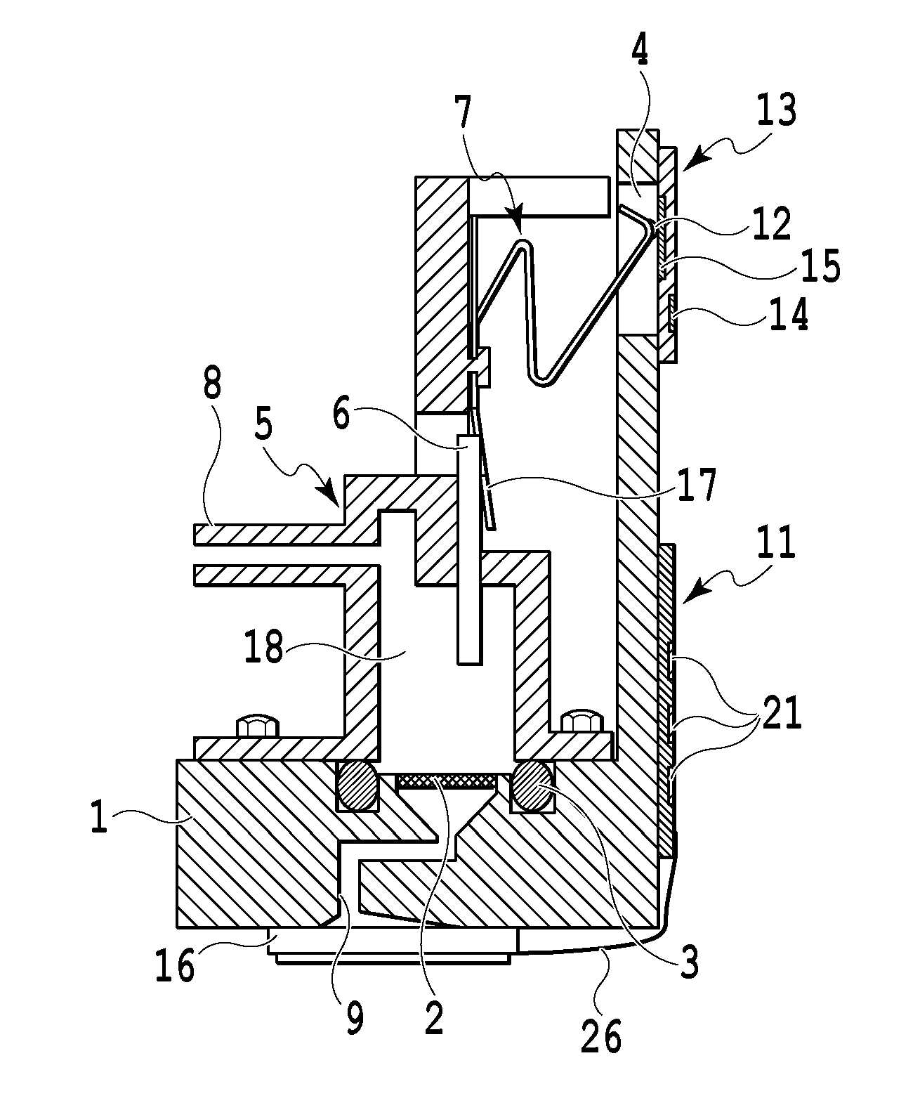
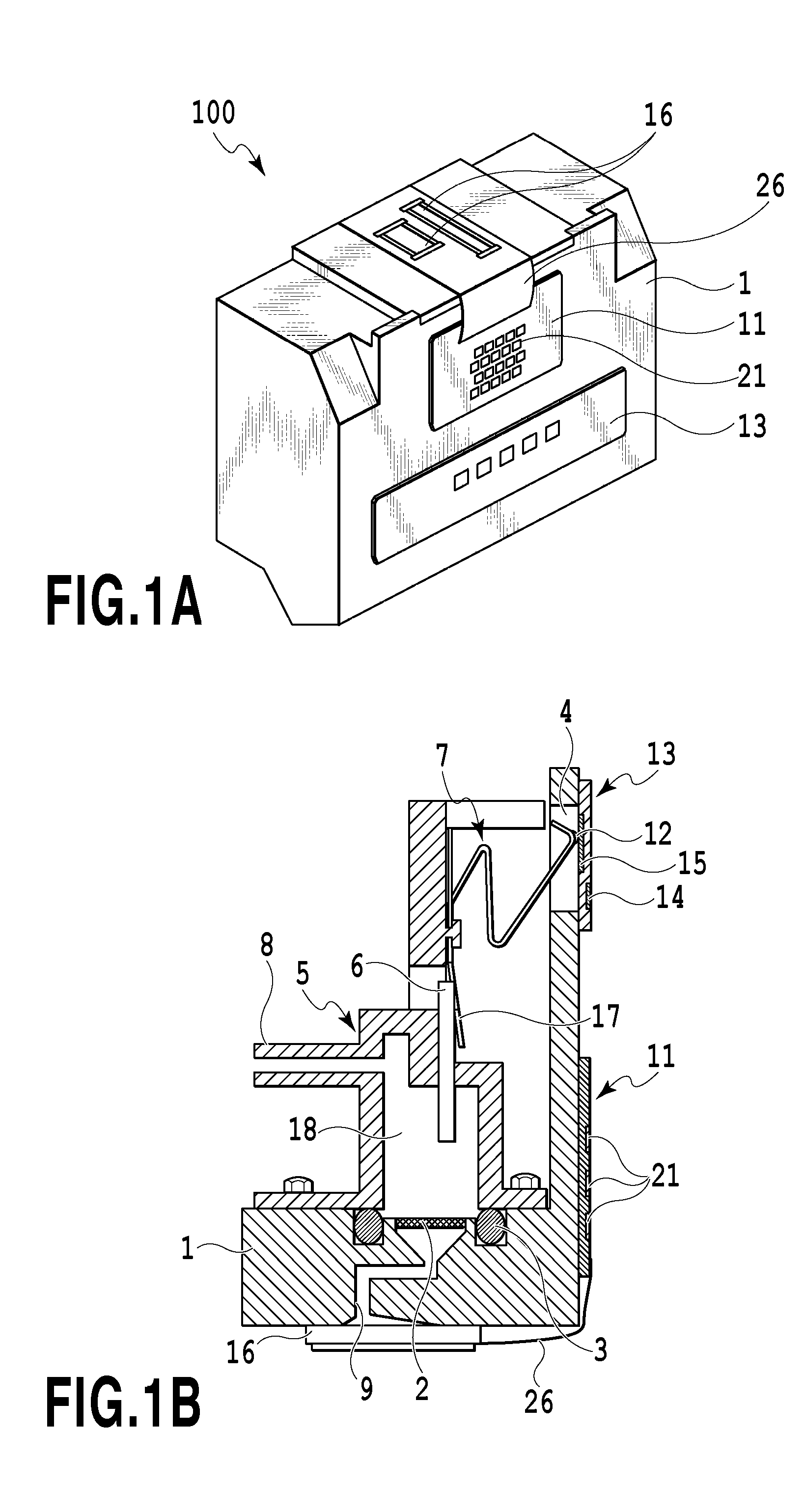
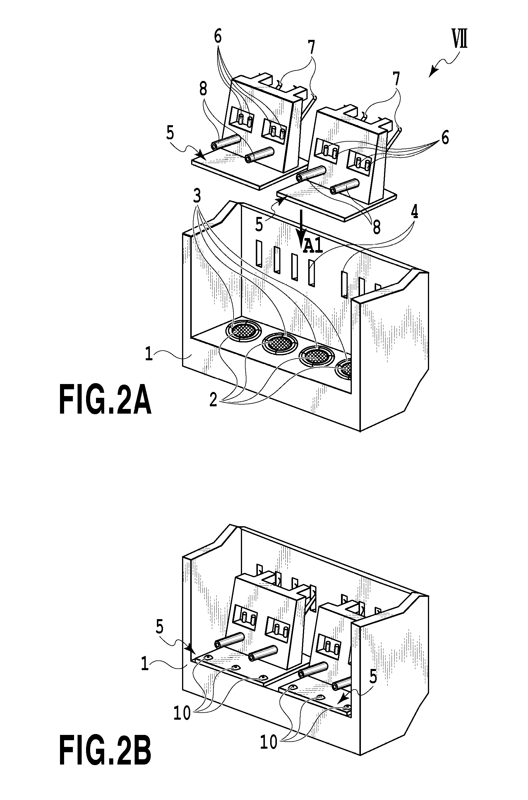
[0026]FIG. 1A is a perspective view showing an inkjet print head 100 in the present embodiment; and FIG. 1D is a cross-sectional view showing the print head 100. FIGS. 2A, 28, 3A, and 3B are perspective views in a step of assembling the print head 100.

[0027]A print element board (i.e., an ejecting unit) is provided with a plurality of ejection ports (not shown), and a plurality of ejection energy generating elements (not shown) such as electrothermal transducers (i.e., heaters) or piezoelectric elements. Ink and electric power are supplied to the print element board 16, so that the ink can be ejected from the ejection port. In a case where the electrothermal transducer is used as the ejection energy generating element, heat generated by the electrothermal transducer foams ink, and then, the use of its foaming energy enables the ink to be ejected from the ejection port.

[0028]The print element board 16 is secured at a position of a casing (i.e., a main body) 1, to which the ink is sup...

second embodiment

[0048]FIG. 8 is a cross-sectional view showing essential parts of a print head in a second embodiment of the present invention.

[0049]In a case where rigidity required for the print head 100 is low, and therefore, the thickness T of the casing 1 can be reduced, the length of the through hole 4 can be reduced, like the thickness T, thus reducing a largest displacement required for the bent portion R1 (i.e., the contact 12) in directions indicated by arrows B1 and B2. In this case, it is desirable that the number of bent portions to be formed at the flat spring 7 should be reduced from the viewpoint of the stability of the shape of the flat spring 7, like the present embodiment. Three bent portions R1, R2, and R3 and two flat portions L1 and L2 are formed at the flat spring 7. Thus, it is possible to secure the displacement of the flat spring 7 according to the short through hole 4 so as to stably deform the flat spring 7.

third embodiment

[0050]FIG. 9 is a cross-sectional view showing essential parts of a print head in a third embodiment of the present invention.

[0051]In a case where rigidity required for the print head 100 is high, and therefore, the thickness T of the casing 1 is increased, the length of the through hole 4 can be increased, like the thickness T, thus increasing a largest displacement required for the bent portion R1 (i.e., the contact 12) in directions indicated by arrows B1 and B2. In this case, it is possible to increase the number of bent portions to be formed at the flat spring 7 so as to secure the satisfactory displacement of the flat spring 7 according to the long through hole 4, like the present embodiment. Five bent portions R1, R2, R3, R4, and R5 and four flat portions L1, L2, L3, and L4 are formed at the flat spring 7 in the present embodiment.


PUM

PropertyMeasurementUnit
rotational angleaaaaaaaaaa
liquid ejectingaaaaaaaaaa

Abstract

There are provided a liquid ejecting head having a high fabrication efficiency and a high reliability of an electric connector, and a fabricating method for the liquid ejecting head. A direction in which a channel forming member is incorporated to a casing crosses a direction in which a flat spring is resiliently deformed. In incorporating the channel forming member, an abutment portion formed at the flat spring is allowed to abut on the casing, thus deforming the flat spring. The flat spring is brought into contact with an inside contact pad by a resilient restoring force of the flat spring.

Description

BACKGROUND OF THE INVENTION[0001]1. Field of the Invention[0002]The present invention relates to a liquid ejecting head for ejecting liquid such as ink and a fabricating method for the liquid ejecting head.[0003]2. Description of the Related Art[0004]A liquid ejecting head is exemplified by an inkjet print head that is mounted on an inkjet printing apparatus and can eject ink. Japanese Patent Laid-open No. S60-34870(1985) discloses a print head provided with a plurality of electrode pins in order to detect a remaining amount of ink staying in an ink channel at the print head. The remaining amount of ink staying in the ink channel can be detected based on a change of an electric resistance between the plurality of electrode pins. The electric resistance in a case where the ink stays in the ink channel is different from that in a case where no ink stays in the ink channel.[0005]In a case where, for example, a channel forming member for forming the ink channel is formed independently o...

Claims


Application Information

Patent Timeline
Patent Type & Authority Applications(United States)
IPC IPC(8): B41J2/14B41J2/16
CPCB41J2/1433Y10T29/49403B41J2002/14491B41J2/162B41J2/14024B41J2/14072B41J2/17513B41J2/17523B41J2/1753B41J2/17553
Inventor TODA, KYOSUKEKUDO, KIYOMITSUKIMURA, SATOSHI
Owner CANON KK
Why Eureka
Try Eureka