

Displacement joystick with compression-sensitive sensors
a technology of compression-sensitive sensors and joysticks, which is applied in the direction of mechanical control devices, instruments, manual control with single controlling members, etc., can solve the problems of unsatisfactory joysticks in many other applications, the amount of displacement capability, and the consumer's general unconcerned about the type of force or movement detecting sensors
- Summary
- Abstract
- Description
- Claims
- Application Information
AI Technical Summary
Benefits of technology
Problems solved by technology
Method used
Image

Examples
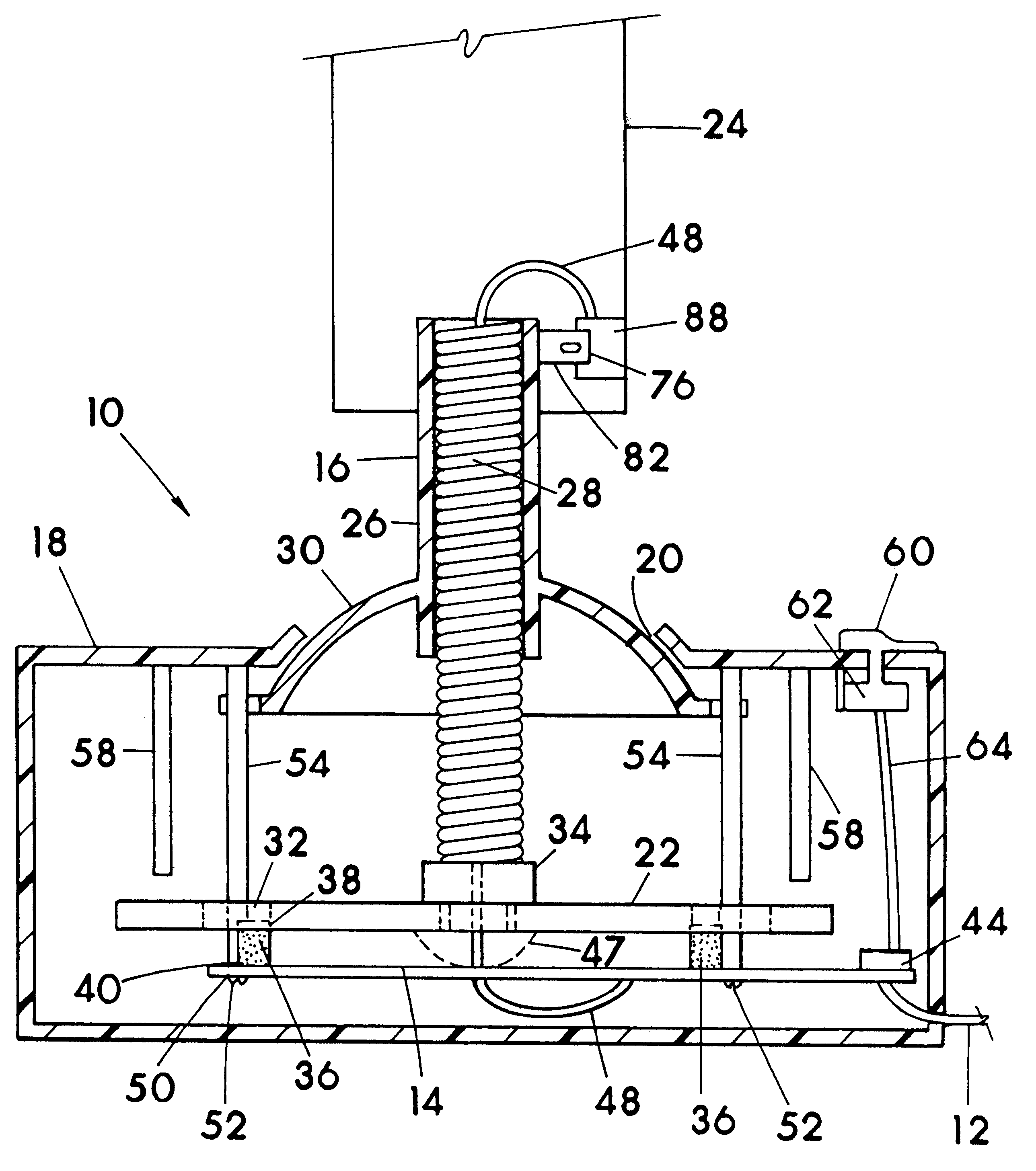
embodiment 10
Arm 16 is moveable or displaceable radially preferably in at least four directions with respect to an axis through the length of the arm from a normal resting position of the arm 16. The displacement of arm 16 is brought about by way of force being applied to an upper region of arm 16, upper meaning further away from base 18. The upper region of arm 16 against which force is applied, such as by a human hand, foot or finger, can be handle 24 on or as a component of arm 16 as in FIG. 1, a tubular sleeve or stem 26 as a component of arm 16 and absent handle 24, or the upper end of spring 28 (resilient member) which when left bare and exposed above base 18 would define arm 16. In joystick embodiment 10, arm 16 can be considered to be spring 28 alone, or spring 28 with stem 26, or spring 28 with stem 26 and handle 24 mounted on stem 26, or arm 16 can be spring 28 with a handle or knob structure mounted directly thereto without the use of stem 26 or an equivalent member.
Spring 28, which i...
embodiment 80
With reference now to FIGS. 9-13 wherein a force detecting sensor arrangement using compression-sensitive variable-conductance sensors 76 of principally the same structure as CSVC sensors 42 are applied for detecting axial rotation of one member relative to another, such as in handle 24 of joystick 10 for sensing rotation about a Z axis or yaw (stem or spring), the direction of rotation and magnitude (amount) of force applied, or in axles 78 of a joystick embodiment 80 which uses a gimbal or double gimbal arrangement, the sensors 76 for sensing direction of rotation of the axles 78 and amount of force applied to the joystick lever arm 82. Such a sensing arrangement can also very economically be used for other axially rotatable members such as those associated with steering wheels for electronic games or the axles or pivot points of foot pedals used for gas, brake or rudder control in electronic games and the like with computers and game machines / consoles, so as to provide analog inf...
PUM
 Abstract
Description
Claims
Application Information