Torsion spring metal ceiling system and hardware

a technology of metal ceiling and steel rod, which is applied in the direction of walls, constructions, building components, etc., can solve the problems of poor registration, irregular joints between panels, and quick and precise positioning, and achieve the effect of eliminating a horizontal positioning function, quick and precise installation, and convenient installation

Active Publication Date: 2015-12-03
USG INTERIORS LLC
View PDF4 Cites 17 Cited by
  • Summary
  • Abstract
  • Description
  • Claims
  • Application Information

AI Technical Summary

Benefits of technology

[0005]The invention is embodied in a novel multi-function clip that attaches a suspension spring to the ceiling panel. The clip enables the spring to hinge through 180 degrees for shipment and for convenient access. The clip, additionally, can hold the spring at a 90 degree orientation relative to the panel to facilitate installation. Besides its role in attaching the suspension spring to the panel, the clip serves to precisely locate the panel on the grid. The locating function of the clip enables the panels to be quickly and precisely installed. As disclosed, the clips can eliminate a horizontal positioning func

Problems solved by technology

Generally, it has been difficult to quickly and precisely position spring mounted panels on the overlying grid with the result that the joints between the panels are often no

Method used


Image

  • Torsion spring metal ceiling system and hardware
  • Torsion spring metal ceiling system and hardware
  • Torsion spring metal ceiling system and hardware

Examples


Embodiment Construction

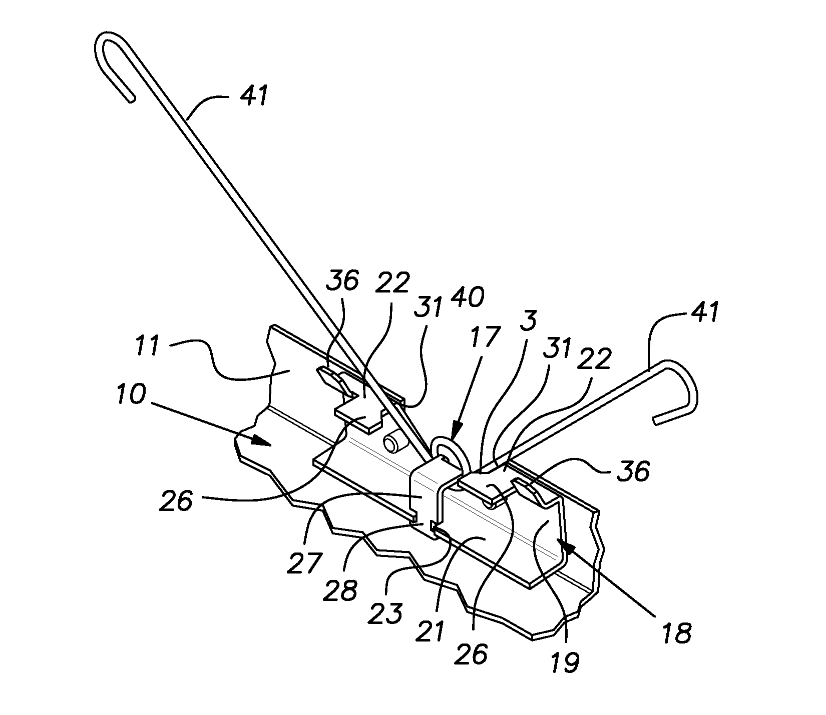
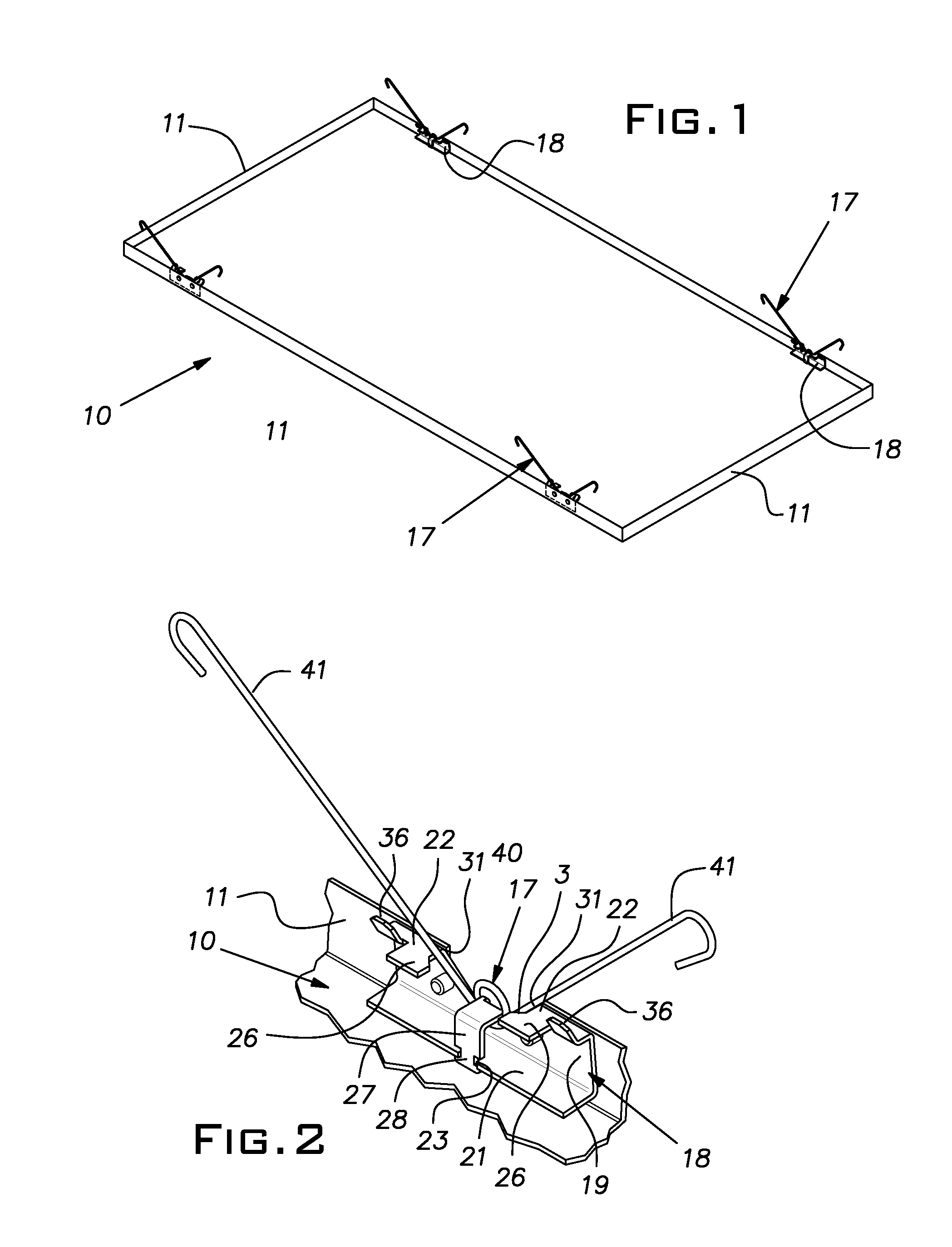
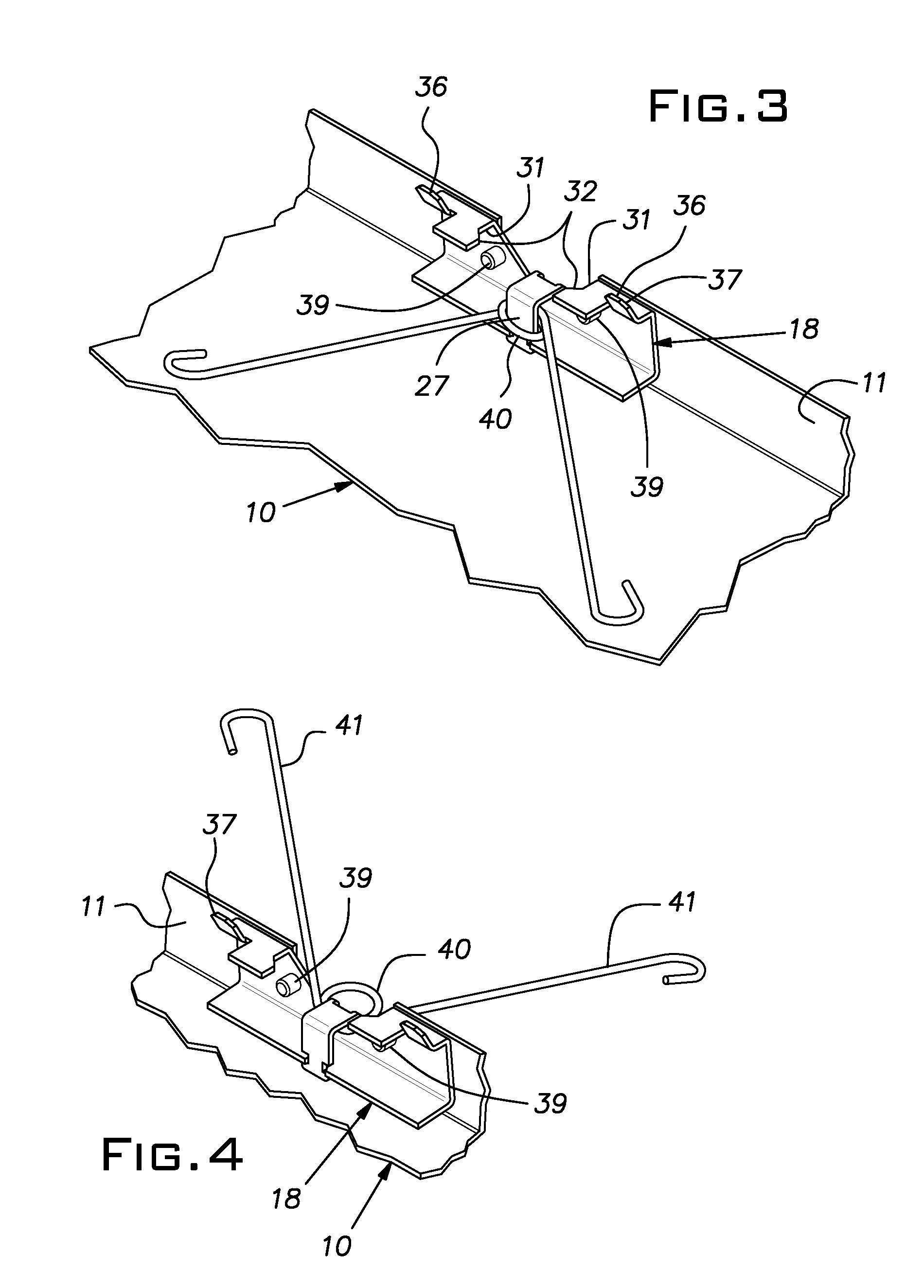
[0016]Referring now to the drawings, a ceiling panel 10 for a suspended ceiling has a rectangular shape which can be square or, as shown in FIG. 1, rectangular. Nominal sizes of the panels include 2 foot×2 foot and 2 foot×4 foot. Dimensions given in this disclosure are intended to include industry metric equivalent dimensions.

[0017]The illustrated panel 10 is formed of sheet metal, typically 0.032 inch gauge aluminum, and has its four edges bent upwardly to form generally vertical sidewalls 11. The sidewalls 11, which give the panel 10 the configuration of a shallow pan, can be nominally 1 inch high from the front face of the panel. The sidewalls 11 can be bent slightly more than 90 degrees so that they form an included angle of, for example, 85 degrees with the plane of the panel 10.

[0018]The panel 10 is used in a conventional manner by attaching it from below to a suspended grid. The grid is typically made from main runners and cross runners, both usually of roll-formed sheet meta...


PUM


Abstract

A rectangular panel for a suspended ceiling, the panel having a suspension spring with two divergent arms at each of two opposed panel edges mounted on a rear side of the panel, each spring being mounted on the panel in an arrangement permitting the arms to lie parallel to a front face of a panel, project rearwardly perpendicular to the front face and to lie outside of the panel parallel to the front face, the spring mounting arrangement enabling the spring to be maintained in the rearward orientation by a force developed by the spring with its arms confined and locator elements for registering the panel with grid members of the ceiling.

Description

BACKGROUND OF THE INVENTION[0001]The invention relates to downwardly accessible suspended ceiling panels.PRIOR ART[0002]One type of suspended ceiling system comprises a grid and panels that rely on springs to hold the panels vertically against the underside of the grid elements. Ordinarily, springs are provided on opposite edges of the panels. Springs can be of the torsion type having a pair of arms extending from a central coil. In a free state, the arm are widely divergent so that when confined by slots or stops at the plane of the grid, the arms draw the panel upwardly against the grid.[0003]It is known to attach the springs in a manner that enables the arms to lie flat against a rear face of the panel for shipping purposes and to extend laterally outwardly from the panel. This latter orientation allows the panel to hang from the grid by the spring arms at one side for convenience when accessing the plenum above the ceiling.[0004]Generally, it has been difficult to quickly and pr...

Claims


Application Information

Patent Timeline
IPC IPC(8): E04B9/00E04B9/04
CPCE04B9/0435E04B9/003E04B9/0478E04B9/068E04B9/26E04B9/06
Inventor UNDERKOFLER, ABRAHAM M.GULBRANDSEN, PEDER J.PAULSEN, MARK R.
Owner USG INTERIORS LLC
Why Eureka
Try Eureka