
Temple support

a technology of support and nose, applied in the field of support, can solve the problems of nose deformation, damage to the skin of the nose, and deformation of the face of the wearer, and achieve the effect of reducing the pressure of the nose pad and preventing deformation of the fa

Inactive Publication Date: 2015-12-03
YANG YOUNG CHUL +1
View PDF3 Cites 1 Cited by
  • Summary
  • Abstract
  • Description
  • Claims
  • Application Information

AI Technical Summary

Benefits of technology

The eyeglasses support described in this patent reduces pressure on the skin of the wearer's nose, preventing deformation of the face due to the weight of the glasses. It can be used with any type of glasses and also allows for the easy attachment of accessories like earrings.

Problems solved by technology

The typical glasses in use constantly depress the skin of the wear's nose with the weight of the frame and lenses, and they block air circulation from dissipating sweat forming on the nose, which may lead to damaged skin or necrosis of the skin of the nose.
In addition, prolonged depression on the nose with the weight of the glasses may cause deformation of the face of the wearer, and especially a patient after a nasal surgery may be unable to wear the glasses.

Method used


Image

  • Temple support
  • Temple support
  • Temple support

Examples


first embodiment

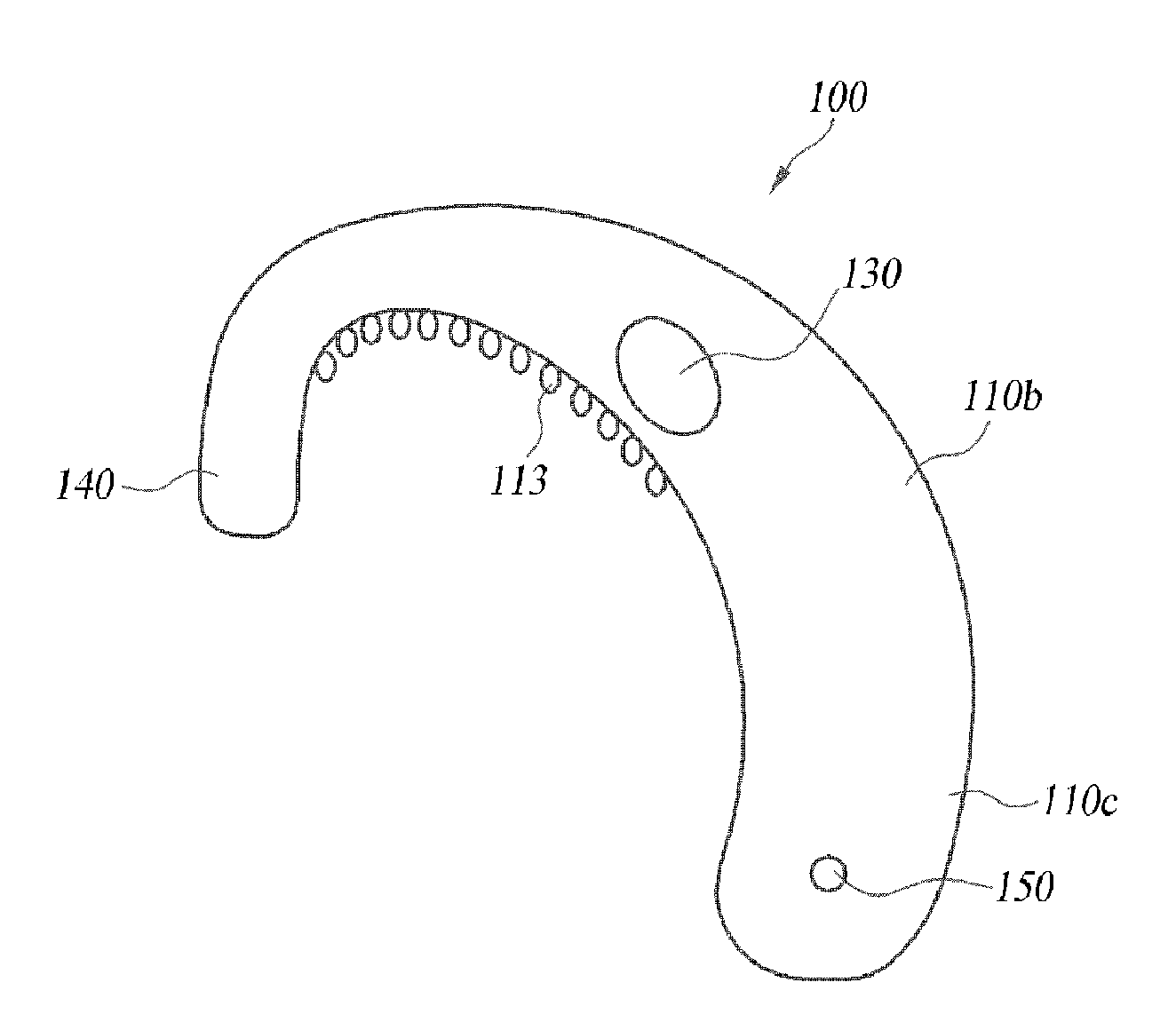
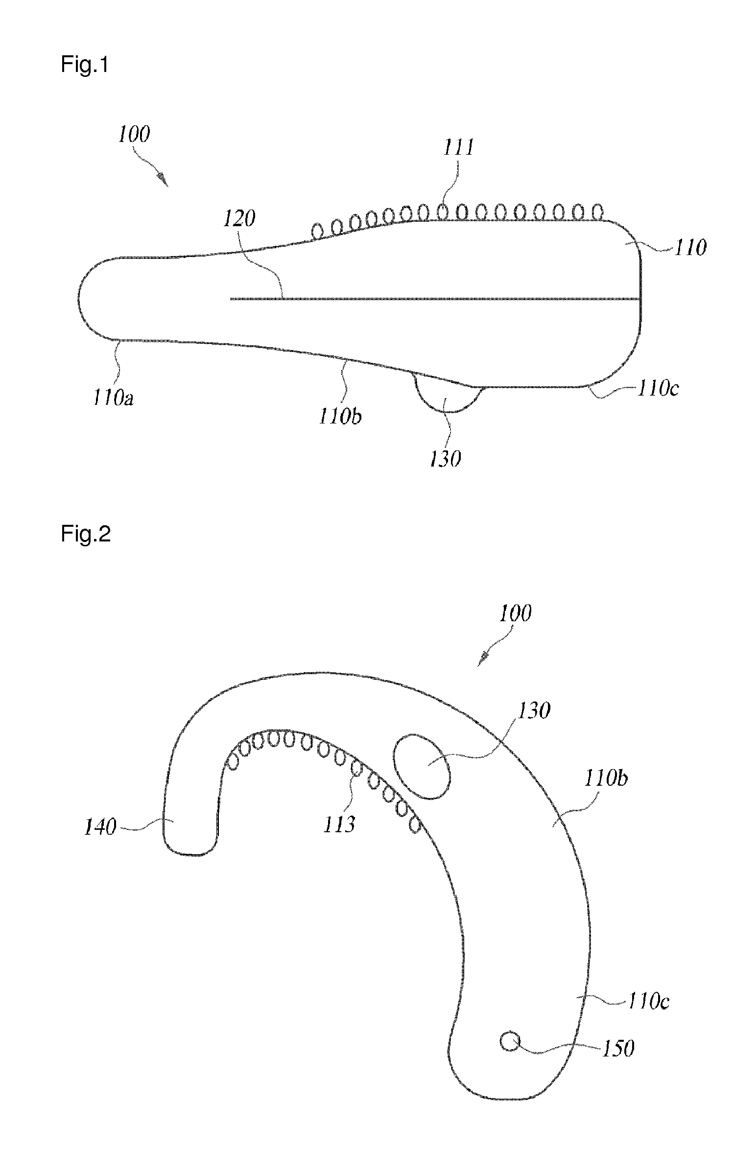
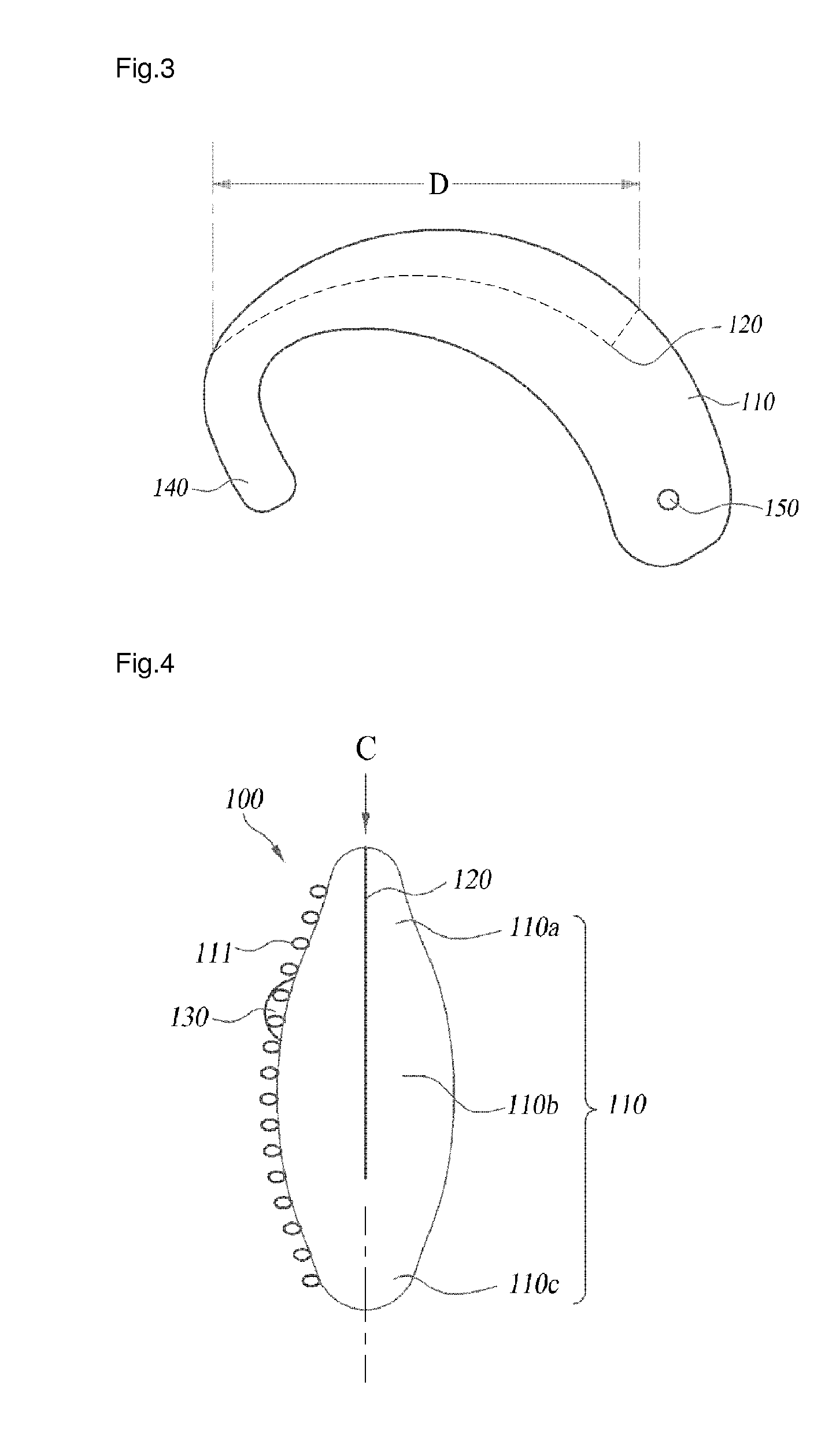
[0028]FIGS. 1 and 4 are plan views of a glasses temple support according to the first embodiment of the present disclosure, FIG. 2 a side view of the temple support, and FIG. 3 a cross-sectional view of the temple support.

[0029]Referring to FIGS. 1 to 3, a temple support for eyeglasses according to the first embodiment of the present disclosure includes a crescent-shaped main body 100, a fixing projection 130 and a temple insertion groove 120. The main body 100 is configured to rest atop the wearer's auricular cartilage where the auricle meets the scalp. The fixing projection 130 is formed integral to the main body 100 and it protrudes from an outer surface of the main body 100. The temple insertion groove 120 is formed in the main body 100 to a predetermined depth from the upper surface thereof.

[0030]The first embodiment of the present disclosure illustrates the linear insertion groove 120 formed in the upper surface of the main body 100, although it may be modified into a sigmoid ...

second embodiment

[0043]Referring to FIGS. 7 to 11, the configuration and operation of a temple support according to a second embodiment of the present disclosure will be described in detail.

[0044]FIG. 7 is a plan view of a glasses temple support according to a second embodiment of the present disclosure, FIG. 8 a side view of the temple support, FIG. 9 a perspective view of the temple support, and FIG. 10 a perspective view of the temple support.

[0045]As illustrated in FIGS. 7 to 11, the temple support for eyeglasses according to the second embodiment of the present disclosure includes a pair of crescent-shaped main bodies 210, at least one fixing projection 230, at least one through groove 220 and at least one slit 240 formed through the main body 210 along the through groove 220. The crescent-shaped main bodies 210 are each configured to rest atop the wearer's auricular cartilage where the auricle meets the scalp. The fixing projection 230 protrudes from the main body 210 at outer surface thereof ...


PUM


Abstract

Disclosed is a temple support which supports a temple to prevent glasses nose pads from coming in contact with the bridge of the nose when wearing glasses, thereby reducing pressing on skin of the bridge of the nose caused by the glasses nose pads. The temple support according to the present disclosure comprises: a crescent-shaped main body portion provided at an upper bone constituting the boundary of the scalp of a wearer and the ear auricle; a fixing protrusion projected on the outer surface of the main body portion in an integrated manner. and a groove for temple insertion which is formed at the upper surface of the main body portion.

Description

TECHNICAL FIELD[0001]The present disclosure in at least one embodiment relates to a temple support for eyeglasses, and more particularly to a temple support that can reduce the nose pad pressure on the skin of the bridge of the wearer's nose.BACKGROUND[0002]Typical glasses are constituted by rims or a frame and a pair of temples hinged to the frame that is provided with a pair of lenses and centrally mounted nose pads.[0003]The typical glasses in use constantly depress the skin of the wear's nose with the weight of the frame and lenses, and they block air circulation from dissipating sweat forming on the nose, which may lead to damaged skin or necrosis of the skin of the nose.[0004]In addition, prolonged depression on the nose with the weight of the glasses may cause deformation of the face of the wearer, and especially a patient after a nasal surgery may be unable to wear the glasses.DISCLOSURE Technical Problem[0005]Some embodiments of the present disclosure have been made in orde...

Claims


Application Information

Patent Timeline
Patent Type & Authority Applications(United States)
IPC IPC(8): G02C5/14G02C3/00
CPCG02C3/003G02C5/143G02C11/00
Inventor YANG, YOUNG CHULYANG, JI YEON
Owner YANG YOUNG CHUL
Learn More