
Millimeter-wave electro-mechanical stripline switch

a technology of electro-mechanical stripline switch and micro-wave, which is applied in the direction of electromagnetic relay details, waveguide type devices, magnetic field micro-mechanical switches, etc., can solve the problems of affecting the operation of the switch or the downstream system, requiring performance trade-offs, and the high-frequency switch employing field-effect transistors (fets) is typically unable to handle high frequencies

Active Publication Date: 2015-12-03
TEKTRONIX INC
View PDF0 Cites 1 Cited by
  • Summary
  • Abstract
  • Description
  • Claims
  • Application Information

AI Technical Summary

Benefits of technology

The invention relates to a microswitch that can switch between two circuit paths using a stripline switch element. The microswitch includes a mounting surface and a sliding waveguide circuit with a fixed waveguide circuit. The sliding waveguide circuit can be moved between first and second activated positions using magnetic clamping to change the reluctance of the magnetic paths. The technical effect of the invention is a compact and reliable microswitch with improved reliability and performance.

Problems solved by technology

In certain current switching applications, this self-actuation can result in catastrophic failure of the switch or downstream systems.
Unfortunately, most or all of these switches require trade-offs on performance as they are unable to operate within all desired features simultaneously including obtaining high switch isolation greater than 15 dBm, high power handling above 24 dBm, and low insertion loss of a fraction of a dB from DC to mm-wave frequencies.
For example, high-frequency switches employing field-effect transistors (FETs) typically are unable to handle high frequencies in the mm-wave range and / or high power above 24 dBm.
In the alternative, FET-based solutions may have high insertion loss.
In addition, waveguide-based switches are difficult to integrate and lack the required bandwidth coverage to DC.
Furthermore, coupling-based diplexers typically have poor isolation and high insertion loss at the cross-over frequency.
However, there is a lack of hot-switchable, small, circuit board mountable switches on the market.
Existing millimeter wave switches are large, connectorized assemblies that are not easily gang-assembled to a circuit board.
Such existing millimeter switches would be difficult, for instance, to use with a Spectrum Analyzer attenuator with 70 dB of dynamic range where 16 SPDT switches may be required.

Method used


Image

  • Millimeter-wave electro-mechanical stripline switch
  • Millimeter-wave electro-mechanical stripline switch
  • Millimeter-wave electro-mechanical stripline switch

Examples


Embodiment Construction

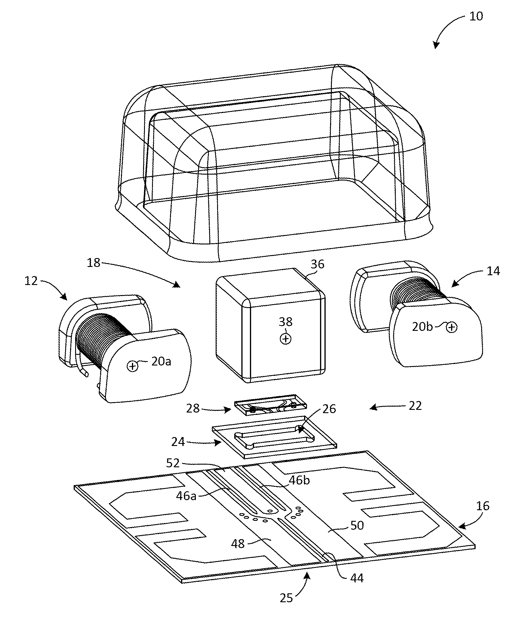
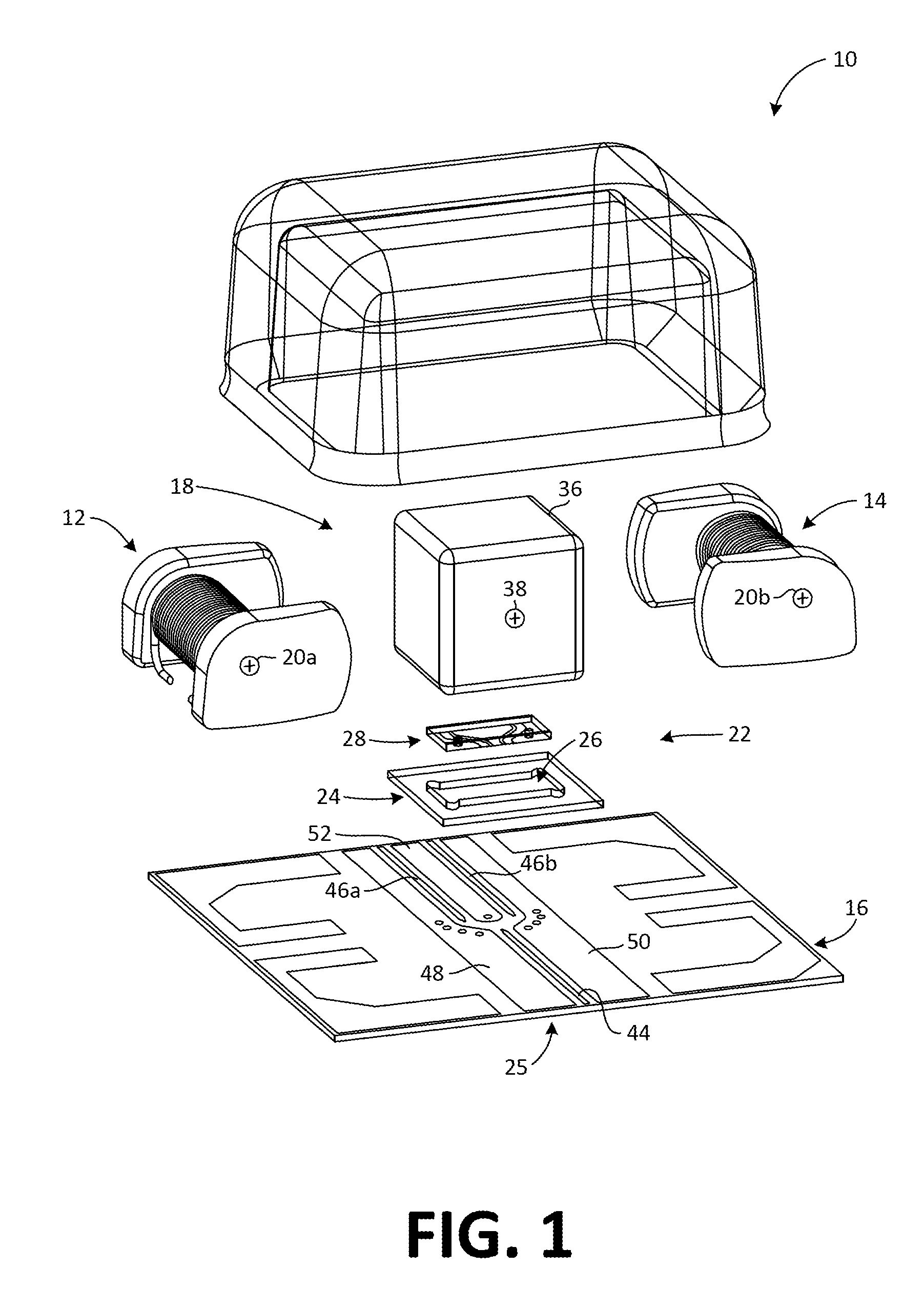
[0018]FIG. 1 is an exploded view of the microswitch 10 constructed according to embodiments of the invention. Microswitch 10 includes first and second electromagnets 12, 14 mounted in spaced-apart orientation to one another on a mounting surface—here, thin film substrate 16—to define a sliding volume 18 [see, e.g., FIG. 6] between them. The first and second electromagnets 12, 14 each have an electromagnetic field center 20a, 20b located a first distance D1 above the mounting surface / substrate 16 [see FIG. 6]. A stripline switch element 22 is mounted to a surface substantially between the first and second electromagnets 12, 14.

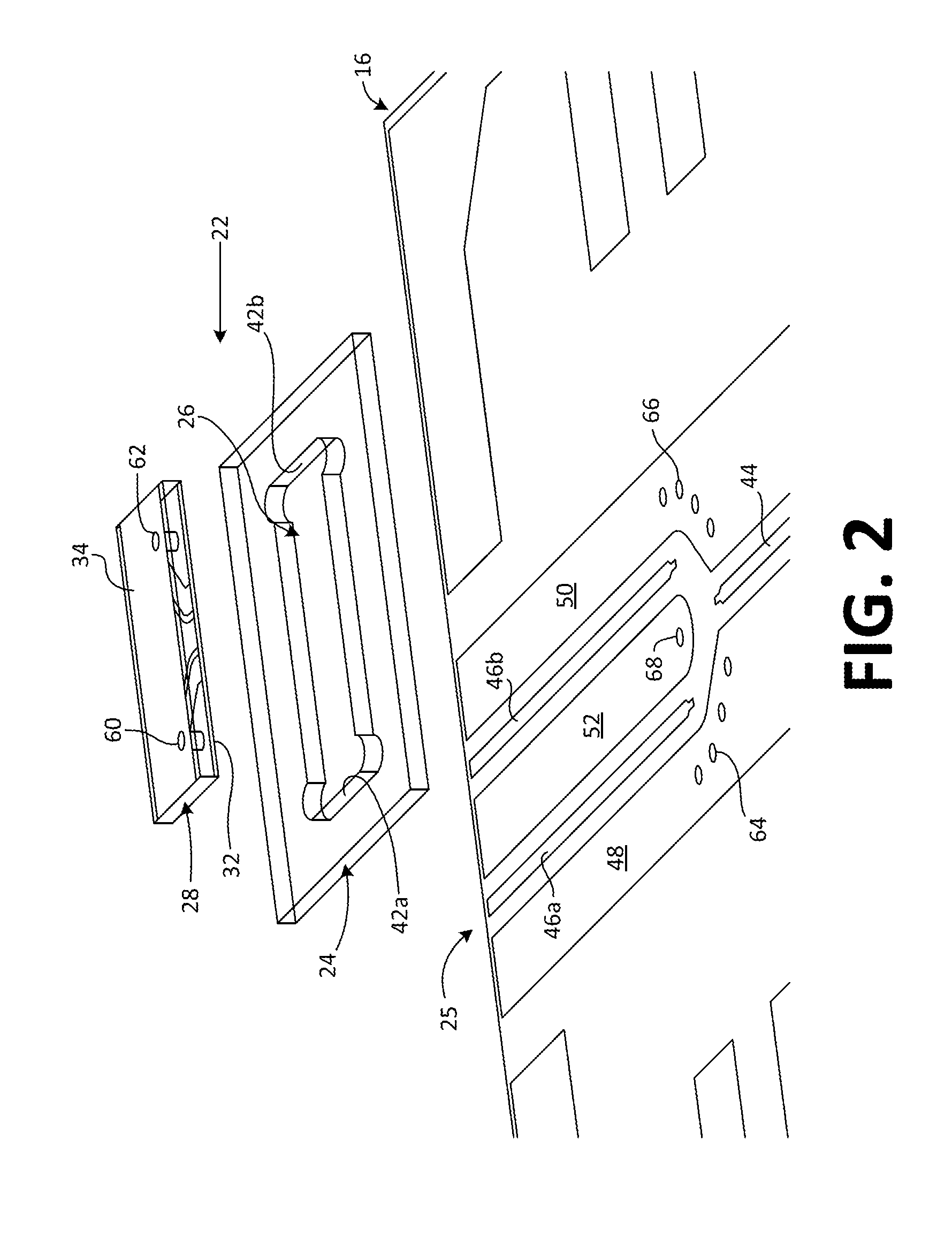
[0019]The stripline switch includes a fixed portion 25 between the first and second electromagnets 12, 14 and a sliding portion 28 positioned in contact with the fixed portion 25. A window 24 is affixed to the fixed portion 25 of the switch 22 and includes a sliding boundary aperture 26 formed therethrough. The aperture opening 26 length is sized larger than th...


PUM


Abstract

An electromechanical microswitch, comprising first and second electromagnets mounted in spaced-apart orientation to one another where each electromagnetic has a field center located a first distance above the mounting surface. A permanent magnet is positioned between the electromagnets and includes a magnetic field center that is higher above the mounting surface than that of the electromagnets so that the permanent magnet is magnetically biased toward the mounting surface. A stripline switch element is mountable between the permanent magnet and mounting surface, and biased against circuit structures on the mounting surface, whereby the stripline switch element moves between first and second activated positions under influence of the electromagnets.

Description

BACKGROUND[0001]This invention relates to microswitches and, more particularly, to electro-mechanical stripline switches mountable to a circuit board.[0002]Switches have long been used in electrical circuit designs to isolate a portion of an electrical circuit. In its simplest form, a switch operates to allow a signal to pass from an input terminal to an output terminal in a “closed” position and to prevent the signal from passing from the input terminal to the output terminal in an “open” position. Other such switches, such as those having a single pole dual throw (SPDT), switch between contacts for different functions.[0003]Micro-electromechanical systems (MEMS) are electro-mechanical devices that generally range in size from a micrometer to a millimeter in a miniature sealed package. In the microwave and mm-wave frequency range, switches are used in instrumentation, communications, radar, fiber optic and many other systems that require high-frequency switching. For example, a swi...

Claims


Application Information

Patent Timeline
Patent Type & Authority Applications(United States)
IPC IPC(8): H01H50/00
CPCH01H50/005H01H59/00H01H51/2209H01P1/127H01H2050/007H01H2051/2218H01H15/005H01H51/01H01H51/2227H01H51/27H01H2036/0093H01H2001/0042
Inventor PILEGGI, JAMES D.HILL, JASON C.
Owner TEKTRONIX INC
Learn More