LED retrofit lamp with shunt capacitors across rectifier diodes for use with a ballast
a technology of rectifier diodes and retrofit lamps, which is applied in the use of semiconductor lamps, lighting and heating apparatus, semiconductor devices for light sources, etc., can solve the problems of power consumption, disclosure of features, and further reduction of the power consumption of led replacement lamps, so as to improve the life of lamps
- Summary
- Abstract
- Description
- Claims
- Application Information
AI Technical Summary
Benefits of technology
Problems solved by technology
Method used
Image
Examples
second embodiment
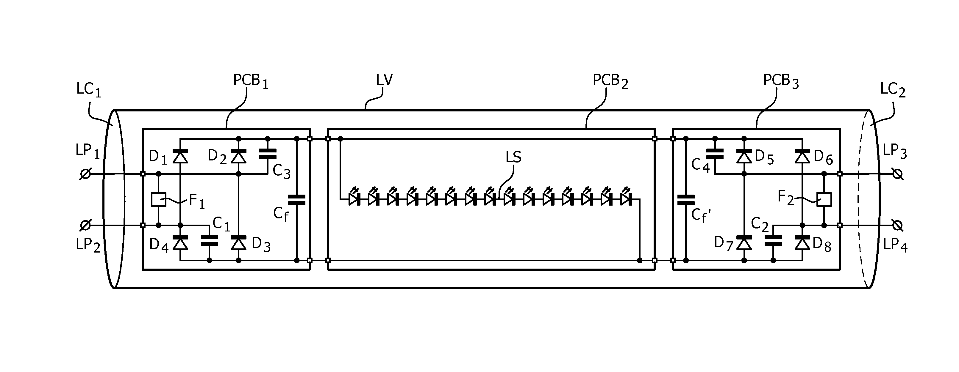
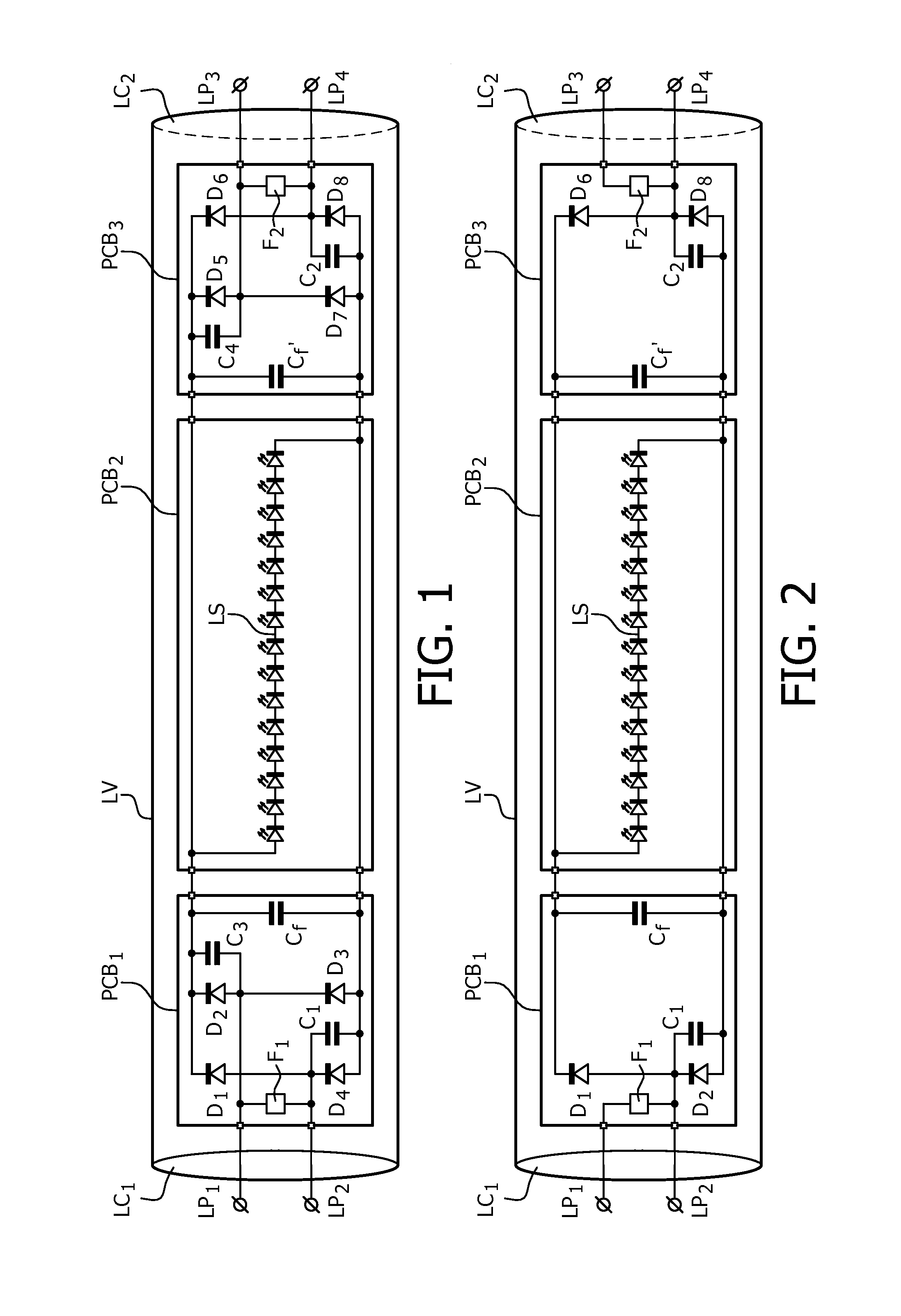
[0039]a LED replacement lamp is shown in FIG. 2. In FIG. 2 components and circuit parts corresponding to components and circuit parts comprised in the embodiment shown in FIG. 1 are labeled with the same reference signs.
[0040]A difference between the embodiment shown in FIG. 1 and the embodiment shown in FIG. 2 are that the first and second rectifiers comprised in the latter only comprise two diodes (D1, D2 and D8, D6 respectively). Furthermore only diode D2 and diode D8 are shunted by capacitor C1 and C2 respectively. Apart from filter capacitors Cf and Cf″ no other capacitors are comprised in the LED replacement lamp. The embodiment in FIG. 2 is cheaper than the one in FIG. 1 since it comprises less components.
[0041]The operation of the LED replacement lamp in FIG. 2 is very similar to the operation of the one shown in FIG. 1. A difference is that the power dissipation in the fusistors F1 and F2 may be bigger than that in the embodiment shown in FIG. 1, because for some lamp confi...
third embodiment
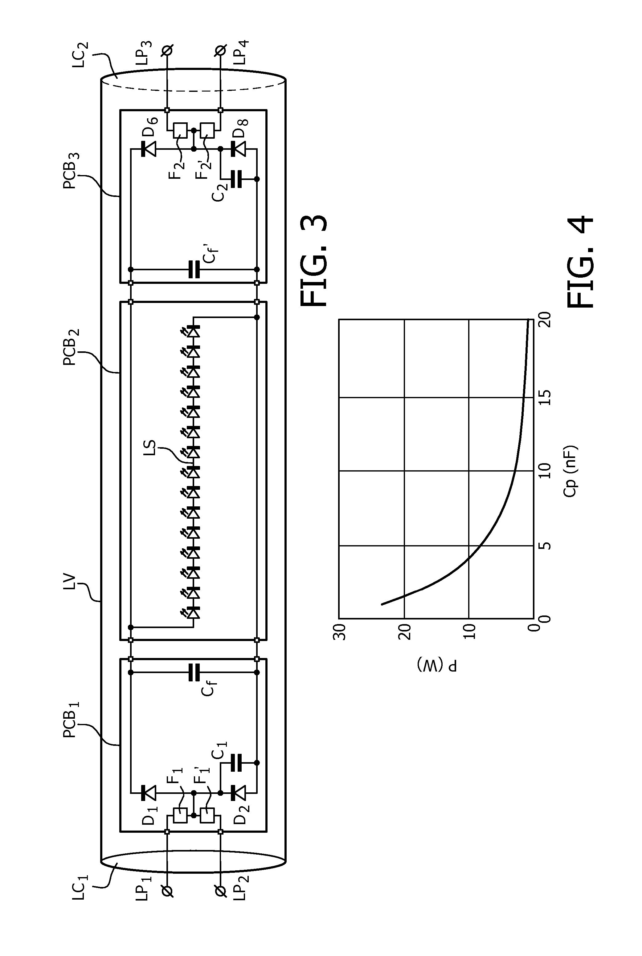
[0043]a LED replacement lamp according to the invention is shown in FIG. 3. Again the same reference signs are used for corresponding components and circuit parts.
[0044]The embodiment shown in FIG. 3 differs from the one shown in FIG. 2, in that the fusistor F1 has been replaced by a series arrangement of two fusistors F1 and F1′ and fusistor F2 has been replaced by a series arrangement of two fusistors F2 and F2′. A common terminal of fusistors F1 and F1′ is connected to a common terminal of diodes D1 and D2 and a common terminal of fusistors F2 and F2′ is connected to a common terminal of diodes D8 and D6.
[0045]The operation of the embodiment shown in FIG. 3 is very similar to that of the embodiments in FIG. 1 and FIG. 2. An important difference is that the fusistors comprised in the embodiments shown in FIG. 1 and FIG. 2 only prevent damage in case the mains voltage is directly connected between lamp pins LP1 and LP2 or between lamp pins LP3 and LP4. In the embodiment shown in FI...
PUM
 Abstract
Description
Claims
Application Information
 - R&D
- Intellectual Property
- Life Sciences
- Materials
- Tech Scout
- Unparalleled Data Quality
- Higher Quality Content
- 60% Fewer Hallucinations
Browse by: Latest US Patents, China's latest patents, Technical Efficacy Thesaurus, Application Domain, Technology Topic, Popular Technical Reports.
© 2025 PatSnap. All rights reserved.Legal|Privacy policy|Modern Slavery Act Transparency Statement|Sitemap|About US| Contact US: help@patsnap.com


