Electro-Optical Display With A Transparent Cover

a technology of electro-optical display and transparent cover, which is applied in the direction of display/control unit casings, instruments, casings of electrical apparatus, etc., can solve the problems that the representation of electro-optical display may be perturbed by the pressure incurred, and achieve the effect of improving configurational freedom, improving fit, and ensuring stability

Active Publication Date: 2015-12-03
CONTINENTAL AUTOMOTIVE GMBH
View PDF16 Cites 49 Cited by
  • Summary
  • Abstract
  • Description
  • Claims
  • Application Information

AI Technical Summary

Benefits of technology

[0010]The electro-optical display obtains a new kind of appearance when the surface of the transparent cover is curved. Because of the bonding material, the representation of the electro-optical display appears undistorted. By this configurational freedom, the electro-optical display can thus be better fitted into an environment which has round shapes rather than rectangular shapes. The configurational freedom is thus increased overall, without restricting the legibility of the electro-optical display.
[0011]Since the structure according to one embodiment of the invention protects the electro-optical display from the effects of external pressure, it can be used ideally in a touch screen. To this end, the touch-screen film is advantageously applied on the transparent cover, since this lies closest to an operating member, for example a finger of the operator or a stylus. If the touch-screen film is laminated onto the transparent cover, it is fastened particularly stably. If the touch-screen film is applied on the side of the transparent cover facing toward the electro-optical display, it is harder to see and is mechanically protected. If the transparent cover is printed on the side facing away from the electro-optical display in its edge region, this printing may be configured in such a way that the frame is no longer perceptible in plan view and a particularly attractive appearance of the electro-optical display can thus be produced. If the transparent cover is colored, a so-called black-screen effect can be achieved so that the electro-optical display is no longer visible when it is switched off, but only the surface of the colored transparent cover is visible. Since reflections by the transparent bonding material are greatly reduced, the transparent cover does not have to be colored very greatly to achieve this effect. The required brightness of the electro-optical display is therefore also not increased excessively.

Problems solved by technology

The representation of the electro-optical display may in this case be perturbed by the pressure incurred, for example when vignetting occurs.

Method used


Image

  • Electro-Optical Display With A Transparent Cover
  • Electro-Optical Display With A Transparent Cover
  • Electro-Optical Display With A Transparent Cover

Examples


Embodiment Construction

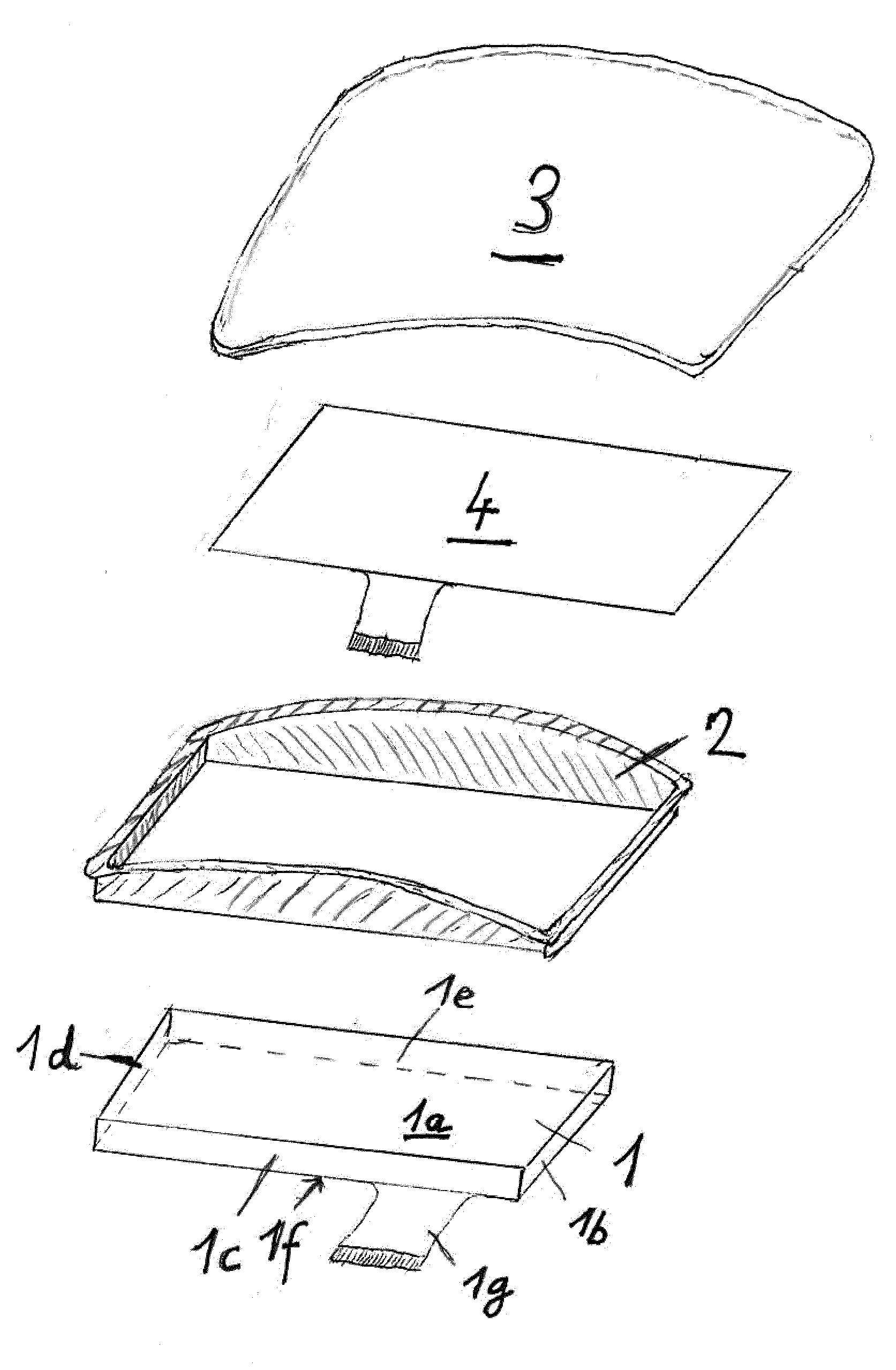
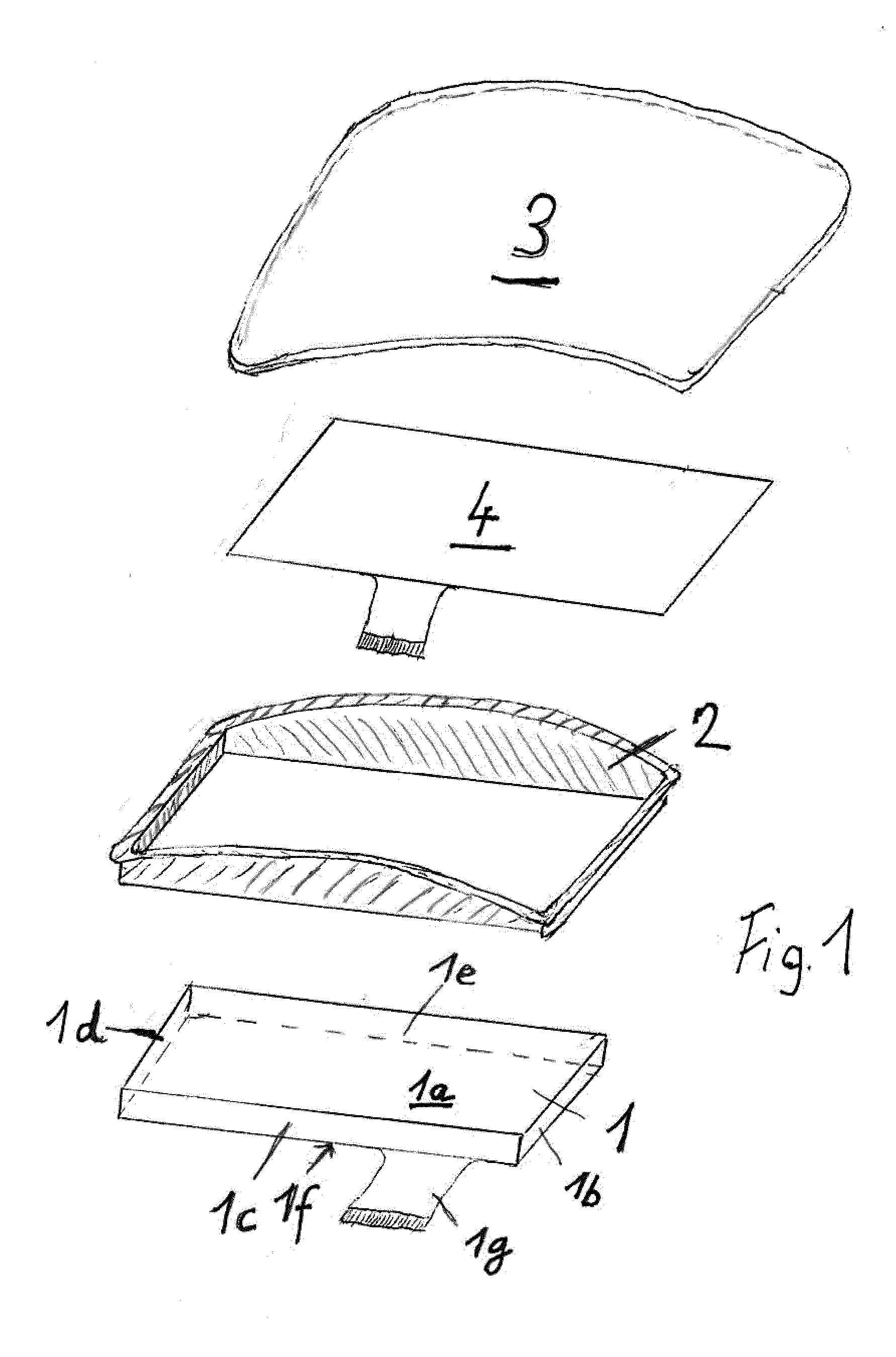
[0015]FIG. 1 shows an electro-optical display 1, a frame 2, a transparent cover 3 and a touch-screen film 4. The electro-optical display 1 has an upper side 1a, side surfaces 1b-1e, a lower side 1f and an electrical connection in the form of a ribbon cable 1g. In the operating state of the electro-optical display, the information represented by the electro-optical display is visible on the upper side 1a of the electro-optical display 1. This information may, for example, be generated by an LCD or an OLED. The electro-optical display 1 is configured in such a way that it fits into the frame 2 with a form fit. It can be seen that the transparent cover 3 has a curved surface, for example in the shape of a section of a cylinder. The transparent cover may likewise be formed in a planar fashion, configured as part of a section of a cone, or configured as any desired freeform surface. For configurational reasons, however, the cover may preferably be configured in a planar fashion or as par...


PUM

PropertyMeasurementUnit
refractive indicesaaaaaaaaaa
transparentaaaaaaaaaa

Abstract

An electro-optical display device with a transparent cover and a display, a transparent bonding material being present between the electro-optical display and the transparent cover, the transparent cover being part of a tray, the sides of the tray being designed as a frame, the lateral surfaces of the electro-optical display being surrounded by the frame in a form-fitting manner and the electro-optical display being connected to the frame.

Description

CROSS REFERENCE TO RELATED APPLICATIONS[0001]This is a U.S. national stage of application No. PCT / EP2013 / 077401, filed on Dec. 19, 2013. Priority is claimed on German Application No. DE102012224352.6, filed Dec. 21, 2012, the content of which is incorporated herein by reference.BACKGROUND OF THE INVENTION[0002]1. Field of the Invention[0003]The invention relates to an electro-optical display with a transparent cover.[0004]2. Detailed Description of the Prior Art[0005]Electro-optical displays, for example liquid-crystal displays or OLEDs, are known from the prior art, having a transparent bonding material present between the electro-optical display and the transparent cover. The electro-optical display is protected by this additional transparent cover. The bonding material known from the prior art adhesively bonds the electro-optical display to the transparent cover, and has the effect that the gap between the electro-optical display and the transparent cover cannot be seen, or can b...

Claims


Application Information

Patent Timeline
Patent Type & Authority Applications(United States)
IPC IPC(8): H05K5/03H01L27/32H05K5/02H05K5/06G02F1/1333H05K5/00
CPCH05K5/03G02F1/133308H05K5/0017G02F2001/133331H05K5/069H01L27/3244H05K5/0217G02F1/13338G02F2202/28G02F1/13332G02F1/133311G02F1/133331H10K59/12
Inventor WILDNER, STEFFENHOHMANN, KAIWEDEL, HANSBOLTE, PETER
Owner CONTINENTAL AUTOMOTIVE GMBH
Why Eureka
Try Eureka