
Engine starting apparatus

Inactive Publication Date: 2015-12-10
DENSO CORP
View PDF7 Cites 4 Cited by
  • Summary
  • Abstract
  • Description
  • Claims
  • Application Information

AI Technical Summary

Benefits of technology

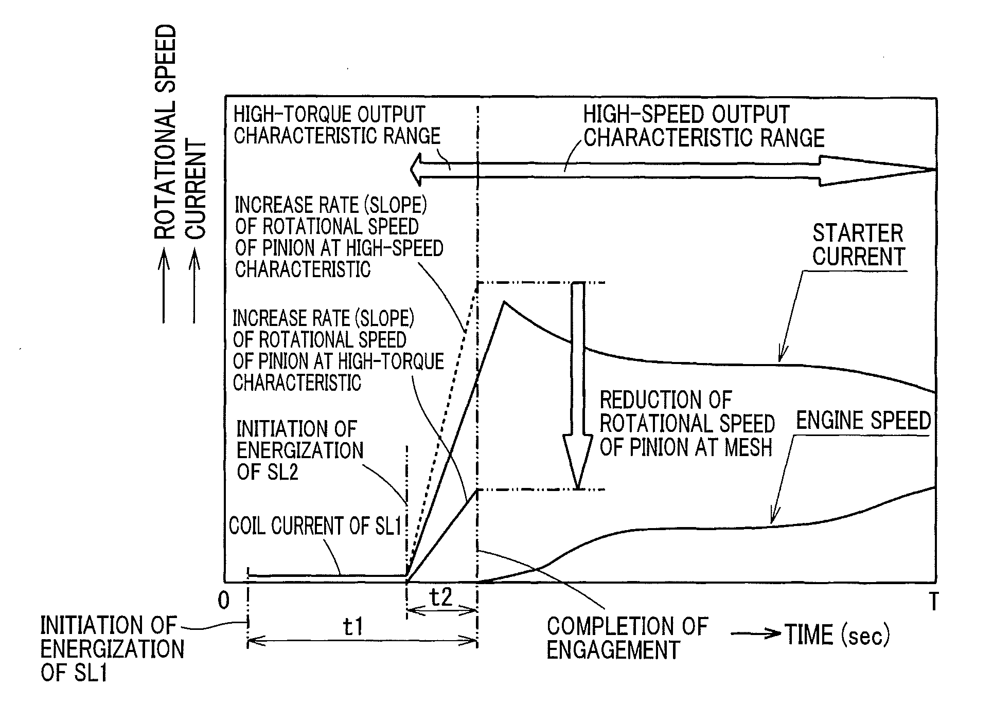
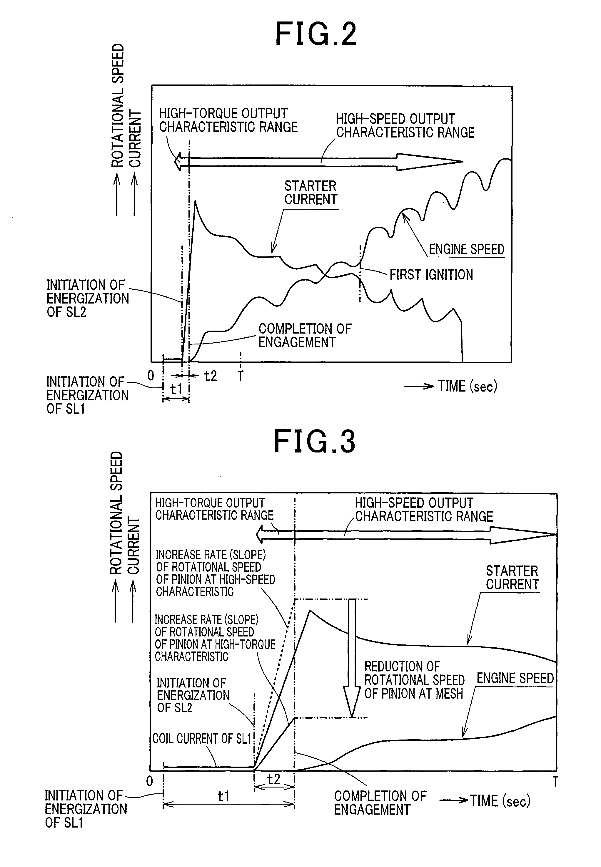
This patent describes an apparatus for starting an engine with a starter. The apparatus uses a solenoid to push the starter pinion towards the ring gear, allowing them to successfully mesh. The starter characteristic is set to a high-torque low-speed, reducing the rotational speed of the pinion at mesh compared to the standard starting speed. This increases the reliability of the engagement. After the pinion is successfully meshed, the starter characteristic switches to a low-torque high-speed characteristic, reducing the elapsed time until the engine start. This improves the comfort of the driver or other occupants of the vehicle.

Problems solved by technology

At the high-speed characteristic of the starter, however, a rotational speed of a pinion may become too high for the pinion to reliably mesh with a ring gear, which may lead to diminished engagement reliability.
This may lead to larger dimensions of the solenoid, thus leading to degradation of installation property of the starter and an increased starter cost.

Method used


Image

  • Engine starting apparatus
  • Engine starting apparatus
  • Engine starting apparatus

Examples


first embodiment

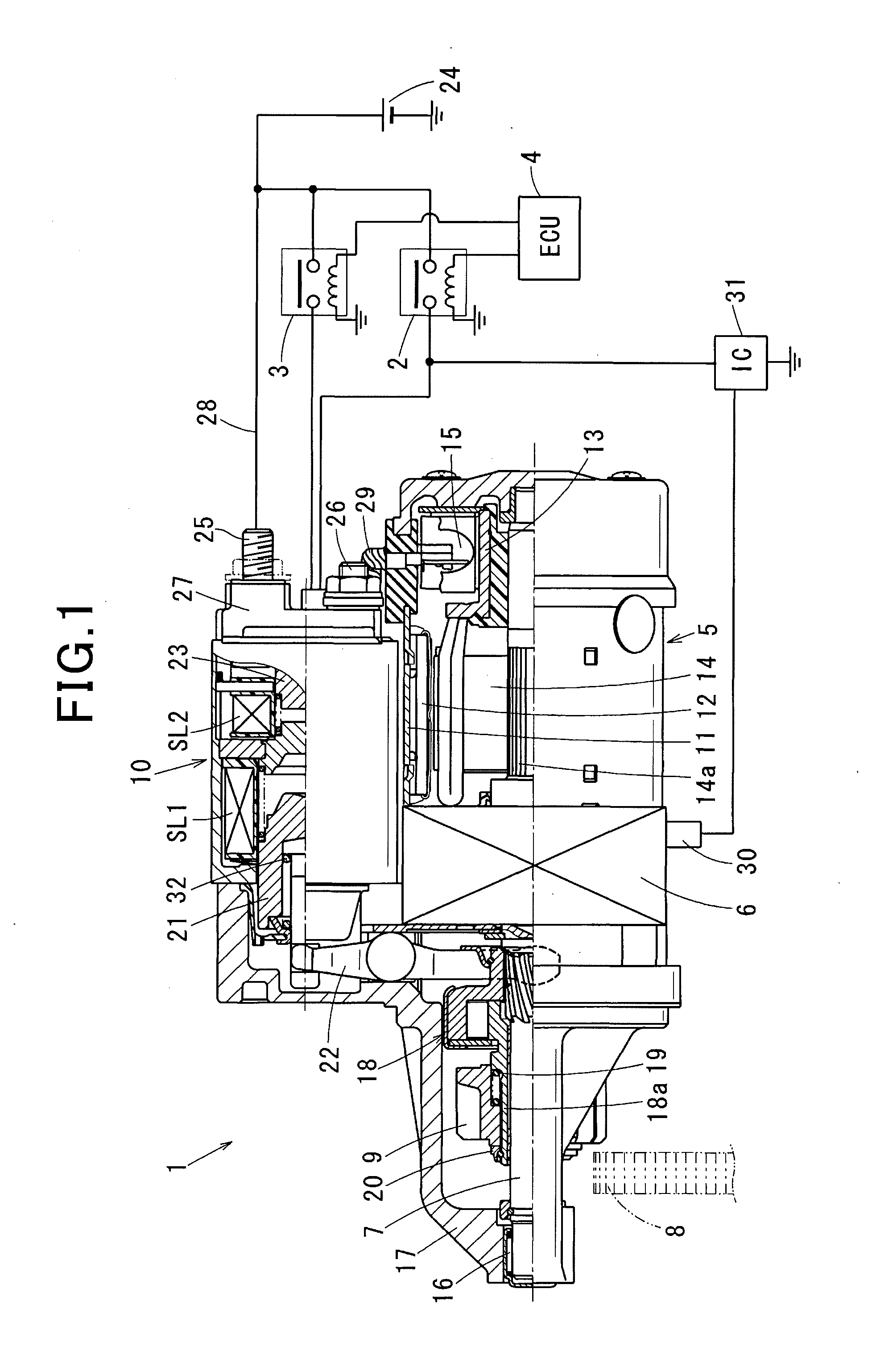
[0019]An engine starting apparatus of a first embodiment is, as shown in FIG. 1, an inertia-engagement-type starter 1, a controller (hereinafter referred to as an electronic control unit (ECU)) 4 configured to control operations of the starter 1 via starter relays 2, 3, and a starter-characteristic switching mechanism (described later) configured to switch output characteristics of the starter 1 (hereinafter referred to as starter characteristics).

[0020]The starter 1 includes a motor 5 configured to generate a rotational force, an output shaft 7 to which the rotational force of the motor 5 is transferred via a variable reducer 6 (described later), a pinion 9 configured to transfer a drive torque of the motor 5 to a ring gear 8 of an engine, an electro-magnetic solenoid device 10 (described later), and other components.

[0021]The motor 5 is a brushed direct-current (DC) motor that includes a field element formed of permanent magnets arranged on an inner periphery of a yoke 11, an arma...

second embodiment

[0046]The starter 1 of the first embodiment includes the variable reducer 6 for switching the starter characteristic between the two different characteristics, i.e., the low-torque high-speed characteristic and the high-torque low-speed characteristic. Alternatively, in the second embodiment, a plurality of such variable reducers 6 may be combined in series with each other, where the operational modes of the respective variable reducers 6 may be individually switched by the mode switcher 30. This allows the starter characteristic to be switched between at least three different characteristics, that is, the starter characteristic may be switched in at least three stages.

[0047]With this configuration, the output characteristic of the starter at mesh may be set to an output characteristic that is lower in torque than the highest-torque characteristic and higher in torque than the output characteristic at which the engine is cranked.

[0048]At such a high-torque low-speed characteristic, ...


PUM


Abstract

An apparatus for starting an engine, including an inertia-engagement-type starter. In the apparatus, a starter-characteristic switching mechanism is configured to switch an output characteristic of the starter between a plurality of output characteristics including at least a low-torque high-speed characteristic and a high-torque low-speed characteristic, where the output characteristic of the starter is hereinafter referred to a starter characteristic. A timing controller is configured to control when the starter-characteristic switching mechanism switches the starter characteristic such that the starter characteristic is set to the high-torque low-speed characteristic from initiation of actuation of the starter at least until a pinion successfully meshes with a ring gear, and after the pinion has successfully meshed with the ring gear, the starter characteristic is switched from the high-torque low-speed characteristic to the low-torque high-speed characteristic at which the engine is cranked by the starter.

Description

CROSS-REFERENCE TO RELATED APPLICATION[0001]This application is based on and claims the benefit of priority from earlier Japanese Patent Applications No. 2014-115563 filed Jun. 4, 2014, the descriptions of which are incorporated herein by reference.BACKGROUND[0002]1. Technical Field[0003]The present invention relates to an engine starting apparatus capable of switching an output characteristic of a starter between a low-torque high-speed characteristic and a high-torque low-speed characteristic.[0004]2. Related Art[0005]Conventionally, there is a desire for an idle-stop-enabled starter to reduce an engine restarting time as much as possible to improve the comfort of a driver or other occupants of a vehicle. A technique for reducing the restarting time includes increasing a cranking speed. Such a technique, however, in combination with good start-up performance at low temperatures where engine friction is high, necessitates use of a large in size and high power motor.[0006]A known te...

Claims


Application Information

Patent Timeline
IPC IPC(8): F02N11/08F02N15/04
CPCF02N11/0851F02N15/04F02N11/0859F02N11/0814F02N11/087F02N15/023F02N15/046F02N15/067F02N2015/061F02N2300/102F02N2300/104F02N2300/2002F02N2300/2011
Inventor HIRABAYASHI, TAKASHI
Owner DENSO CORP
Learn More