Premixing apparatus

a technology of premixing apparatus and mixing chamber, which is applied in the direction of burners, combustion types, combustion processes, etc., can solve the problems of unstable gas introduction, inability to supply air or fuel gas depending on the required amount of combustion, so as to increase the negative pressure operating on the gas suction portion, increase the flow resistance, and prevent uneven distribution of fuel-air ratio of the fuel-air mixture.

Active Publication Date: 2015-12-10
RINNAI CORP
View PDF1 Cites 14 Cited by
  • Summary
  • Abstract
  • Description
  • Claims
  • Application Information

AI Technical Summary

Benefits of technology

[0011]In view of the above-mentioned problems, this invention has an advantage of providing a premixing apparatus which is capable of stably introducing a fuel gas also at the time when the flow resistance in the air feed passage is increased, and which is also capable of preventing the occurrence of uneven distribution of fuel-air ratio of the fuel-air mixture.Means for Solving the Problems
[0013]According to this invention, the flow velocity of the air increases at the venturi portion, thereby giving rise to a negative pressure. Therefore, also at the time when the butterfly valve is rotated to a posture at right angles to the longitudinal direction of the air feed passage, thereby increasing the flow resistance in the air feed passage, the fuel gas can be sucked stably from the gas suction portion. Further, since the venturi portion is coaxial with that portion of the air feed passage which is provided with the butterfly valve, negative pressure is generated uniformly over the entire circumference of the venturi portion. Due to this negative pressure, the fuel gas is sucked from the gas suction portion into an entire circumference of that part of the air feed passage which is adjacent to the downstream side of the venturi portion. As a result, the occurrence of uneven distribution of fuel-air ratio of the fuel-air mixture can be prevented.
[0014]In addition, according to this invention, that cross sectional shape of the butterfly valve which is at right angles to the axis of rotation of the butterfly valve shall preferably be a diamond. According to this arrangement, when the butterfly valve is moved into a posture at right angles to the longitudinal direction of the air feed passage, due to the inclination of that surface of the butterfly valve which faces the upstream side of the air feed passage, the air is guided to flow along the circumferential wall surface of the venturi portion. As a consequence, the flow velocity of the air becomes the highest in the neighborhood of the circumferential surface of the venturi portion, and the negative pressure operating on the gas suction portion increases. Therefore, the stability in suction of the fuel gas from the gas suction portion is further improved at the time when the flow resistance in the air feed passage is increased.

Problems solved by technology

However, in case the required amount of combustion falls below a predetermined amount and, as a result, the number of fan revolution falls below a lower limit value of fan revolution at which the proportional characteristics of the air feed amount can be maintained, or in case the proportional valve current (electric current charge to the proportional valve) falls below the lower-limit current at which the proportional characteristics of the gas feed amount can be maintained, the air or fuel gas depending on the required amount of combustion can no longer be supplied.
In this arrangement, too, when the number of fan revolution falls below the lower-limit revolution at which the proportional characteristics of the air feed amount can be maintained, the amount of air or fuel gas depending on the required amount of combustion can no longer be supplied.
This arrangement, however, has a problem in that, in case the flow resistance in the air feed passage is increased, the air is caused to flow only in the second air feed passage and, therefore, that the negative pressure is not generated so much.
As a result, the suction force of the fuel gas becomes weaker, so that stable gas introduction becomes difficult.
As a result, the fuel gas does not successfully get mixed with the air that has been introduced into the first air flow passage, resulting in an uneven distribution of fuel-air ratio.

Method used


Image

  • Premixing apparatus
  • Premixing apparatus
  • Premixing apparatus

Examples


Embodiment Construction

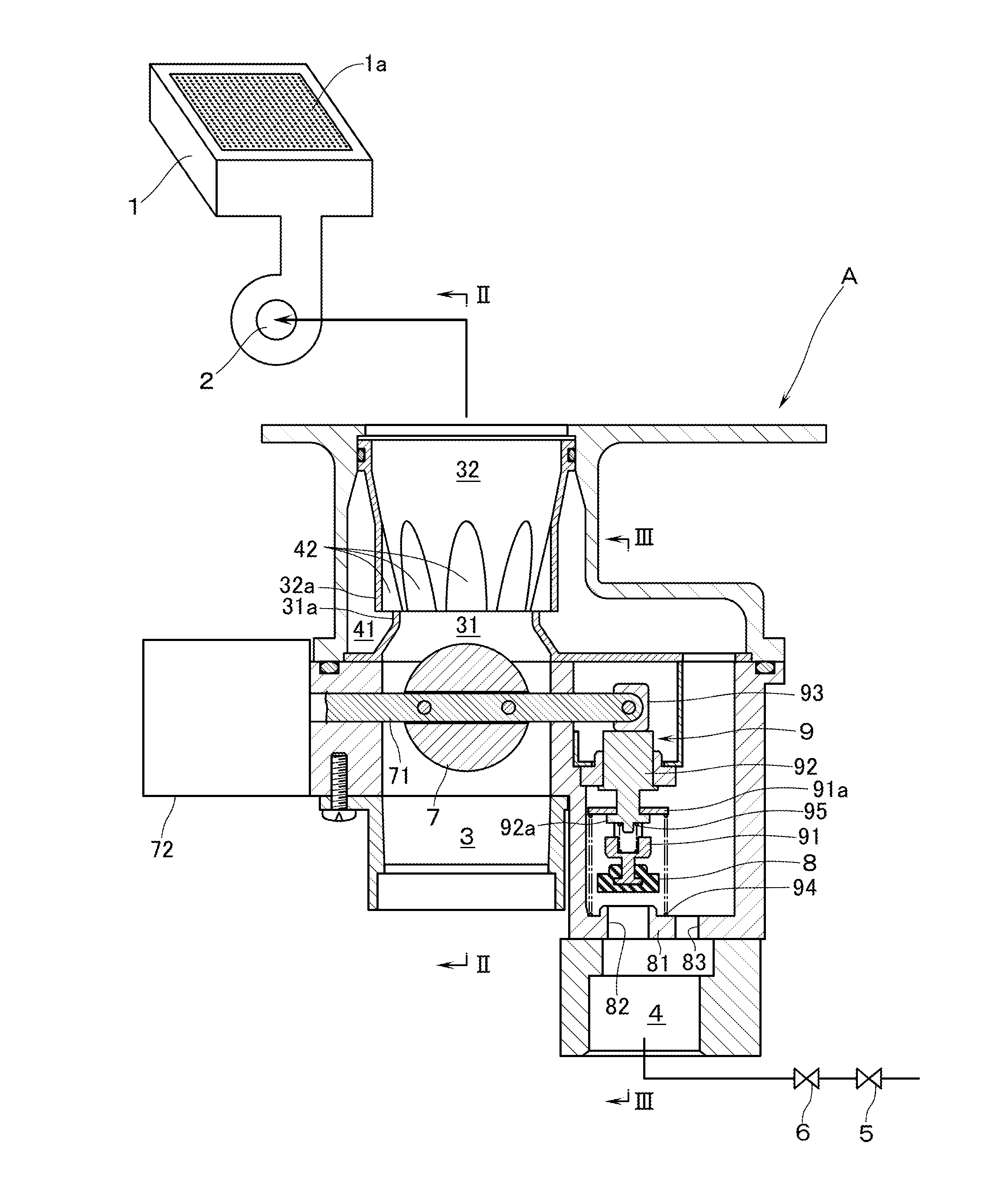
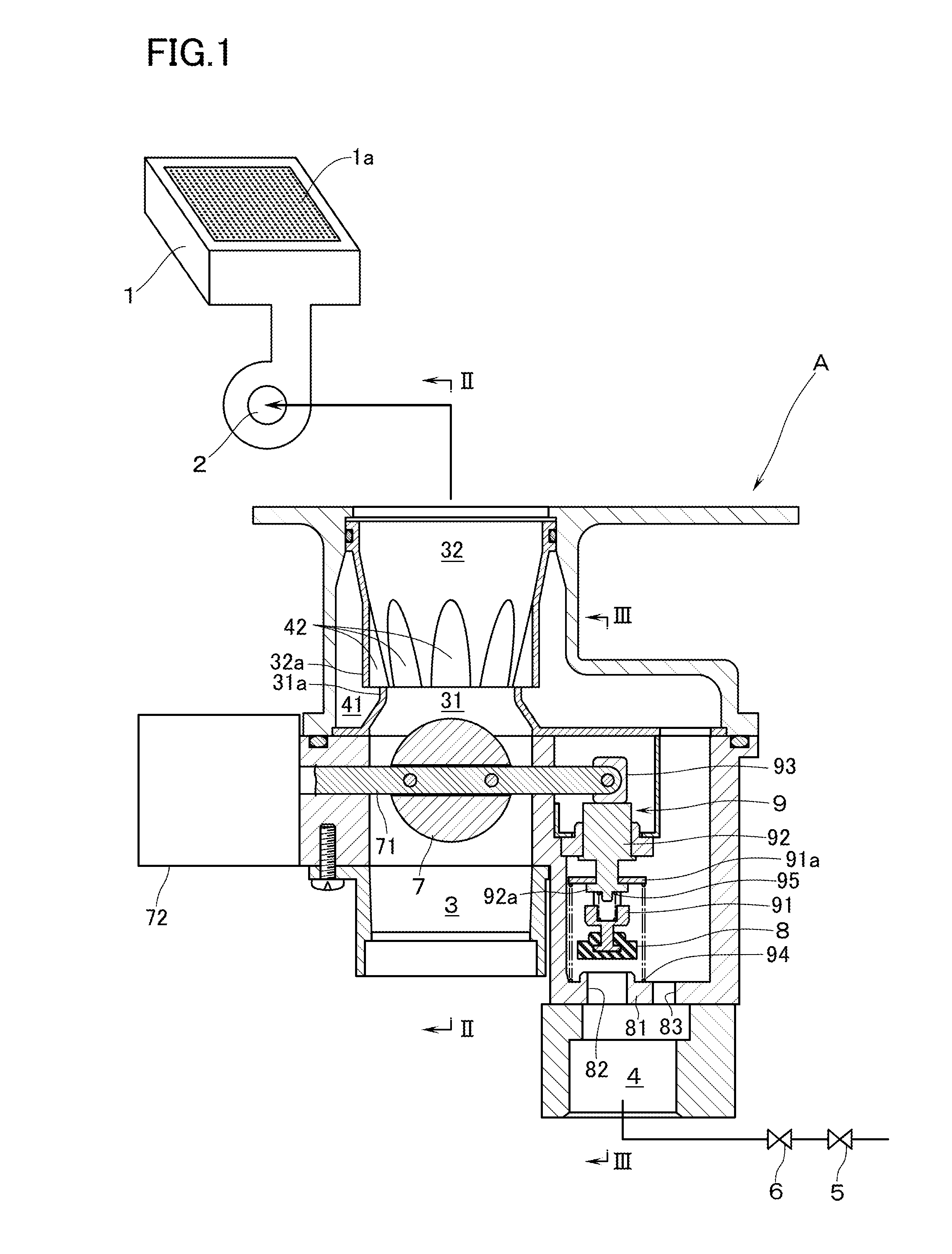
[0019]With reference to FIG. 1, reference numeral 1 denotes a burner comprising a totally aerated combustion burner having a combustion surface 1a in which a fuel-air mixture is ejected for combustion. The burner 1 has connected thereto a fan 2. By means of a premixing apparatus A according to an embodiment of this invention, a fuel gas is mixed with air so that the fuel-air mixture is supplied to the burner 1 through the fan 2.

[0020]The premixing apparatus A is provided on an upstream side of the fan 2 with an air feed passage 3, and a gas feed passage 4 for supplying a fuel gas. On an upstream side of the gas feed passage 4 there are interposed: an on-off valve 5; and a flow control valve 6 which is made up of a proportional valve or a zero governor. Further, the premixing apparatus A is provided with: an air resistance changeover means which changes over, between high and low, a flow resistance in the air feed passage 3; and a gas resistance changeover means which changes over, b...


PUM


Abstract

A premixing apparatus for mixing a fuel gas with air has an air resistance changeover device for changing over a flow resistance in the air feed passage and a gas resistance changeover device for changing over a flow resistance in the gas feed passage. The air resistance changeover device includes a venturi portion provided in that part of the air feed passage which is on a downstream side of the butterfly valve. A gas chamber is provided in that part of the gas feed passage which is on a downstream side of the gas resistance changeover device. A gas suction portion is configured such that the fuel gas is sucked from the gas chamber into an entire circumference of that part of the air feed passage which is adjacent to a downstream side of the venturi portion.

Description

BACKGROUND OF THE INVENTION[0001]1. Field of the Invention[0002]The present invention relates to a premixing apparatus for mixing a fuel gas with air to supply a fuel-air mixture through a fan to a burner.[0003]2. Background of the Related Art[0004]As this kind of premixing apparatus, there is known the following art in Tokkyo Kohyo Koho (National Publication of Translated Version) No. 2014-502719. In the known premixing apparatus, a downstream side of a gas feed passage, in which is interposed a flow control valve for supplying a fuel gas, is connected to an air feed passage on an upstream side of the fan. The premixing apparatus comprises: an air resistance changeover means for changing over, between high and low, a flow resistance in the air feed passage; and a gas resistance changeover means for changing over, between high and low, a flow resistance in that part of the gas feed passage which is on a downstream side of the flow control valve (note: the expression of “that part of...

Claims


Application Information

Patent Timeline
Patent Type & Authority Applications(United States)
IPC IPC(8): F23D14/04
CPCF25J2240/60F23D14/04
Inventor NAKATANI, TATSUYOSHIUOZAKI, MITSURU
Owner RINNAI CORP
Why Eureka
Try Eureka