Microfluidic system, sample analysis device, and target substance detection/measurement method

a microfluidic system and sample analysis technology, applied in the direction of positive displacement liquid engines, instruments, laboratory glassware, etc., can solve the problems of large apparatus, insufficient utilization of the compact structure of the microfluidic system, and delay in reaction time and sample solution, etc., to achieve stably introducing and small dead volume

Inactive Publication Date: 2007-05-31
SEIKO EPSON CORP
View PDF13 Cites 15 Cited by
  • Summary
  • Abstract
  • Description
  • Claims
  • Application Information

AI Technical Summary

Benefits of technology

[0008] An advantage of some aspects of the invention is to provide a microfluidic system capable of stably introducing a sample solution to a fine flow path in a microfluidic chip while controlling the introducing speed, the microfluidic system being one in which bubbles cannot easily enter the flow path and the dead volume is small.

Problems solved by technology

Moreover, because the volume in the capillaries is dead volume, the reaction time delays and the sample solution is wasted.
Furthermore, the whole apparatus becomes large when capillaries are used for connection, and as a result, the advantage of the compact structure of the microfluidic system cannot be fully utilized.
Moreover, with this structure, bubbles cannot easily enter the connecting part because capillaries are not used much for connection.

Method used


Image

  • Microfluidic system, sample analysis device, and target substance detection/measurement method
  • Microfluidic system, sample analysis device, and target substance detection/measurement method
  • Microfluidic system, sample analysis device, and target substance detection/measurement method

Examples


Embodiment Construction

[0037] Preferred embodiments of the present invention will be described below with reference to the drawings.

Microfluidic System and Microfluidic Chip

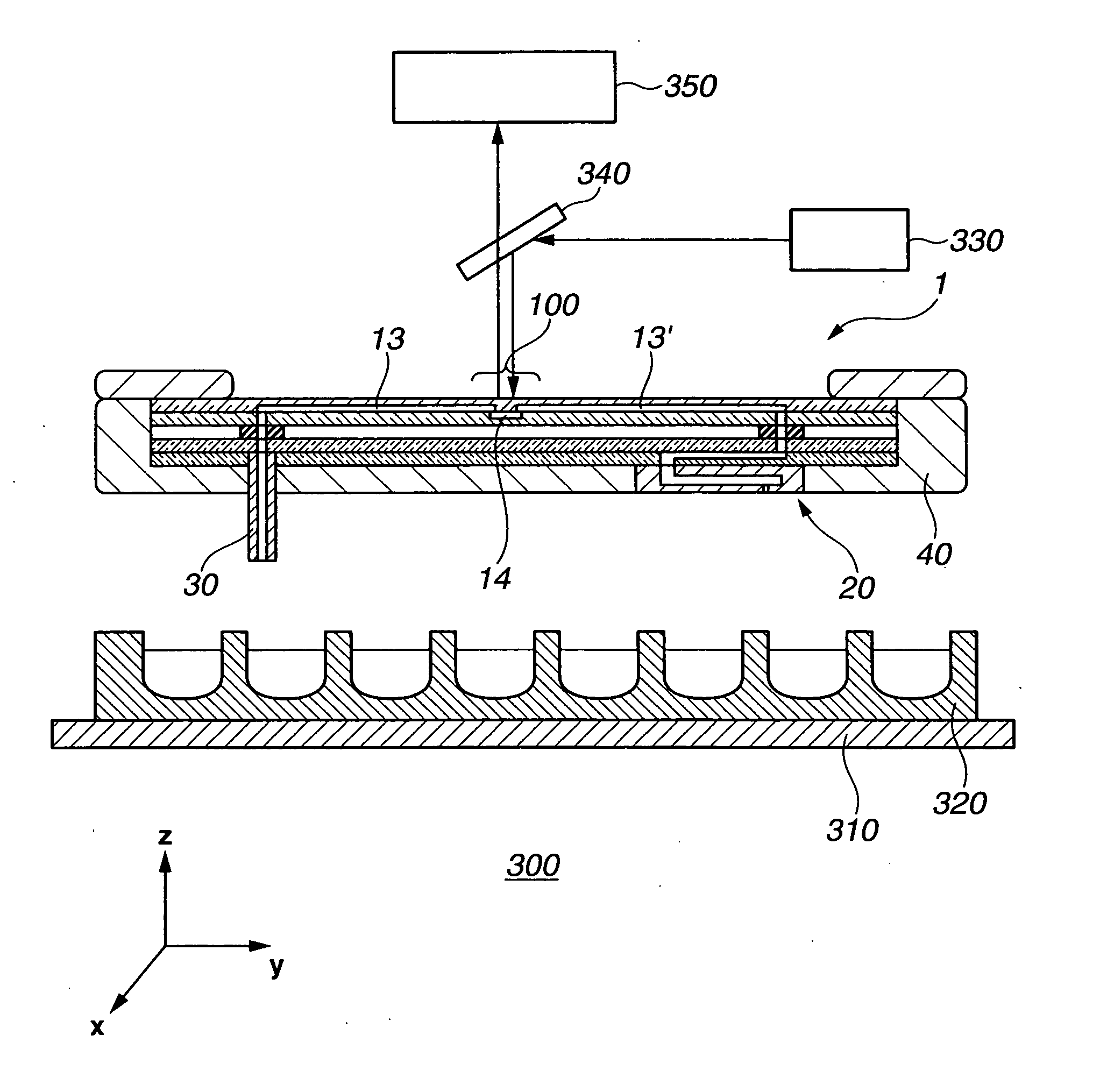
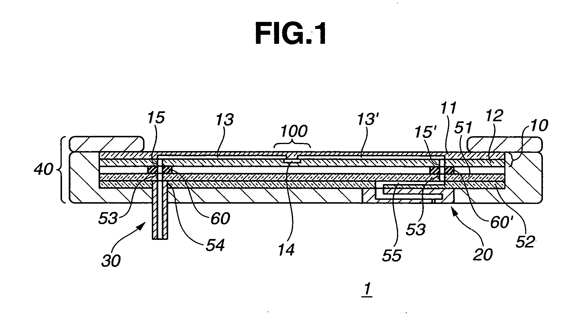
[0038]FIG. 1 shows the schematic cross sectional view of a microfluidic system 1 according to an aspect of the present invention.

[0039] The microfluidic system 1 includes a plate-shaped microfluidic chip 10 having continuous flow paths 13, 14, and 13′, a cylindrical liquid introduction tube 30 connected to an end of the flow path 13 for supplying liquid to the flow paths 13, 14, and 13′, and a liquid discharge head 20 connected to an end of the flow path 13′ for discharging the liquid that has passed through the flow paths 13, 14, and 13′.

[0040] The microfluidic system 1 is held by a holder 40, to which the plates 51 and 52 having the flow paths are fixed. The liquid discharge head 20 and the liquid introduction tube 30 are also fixed to the holder 40.

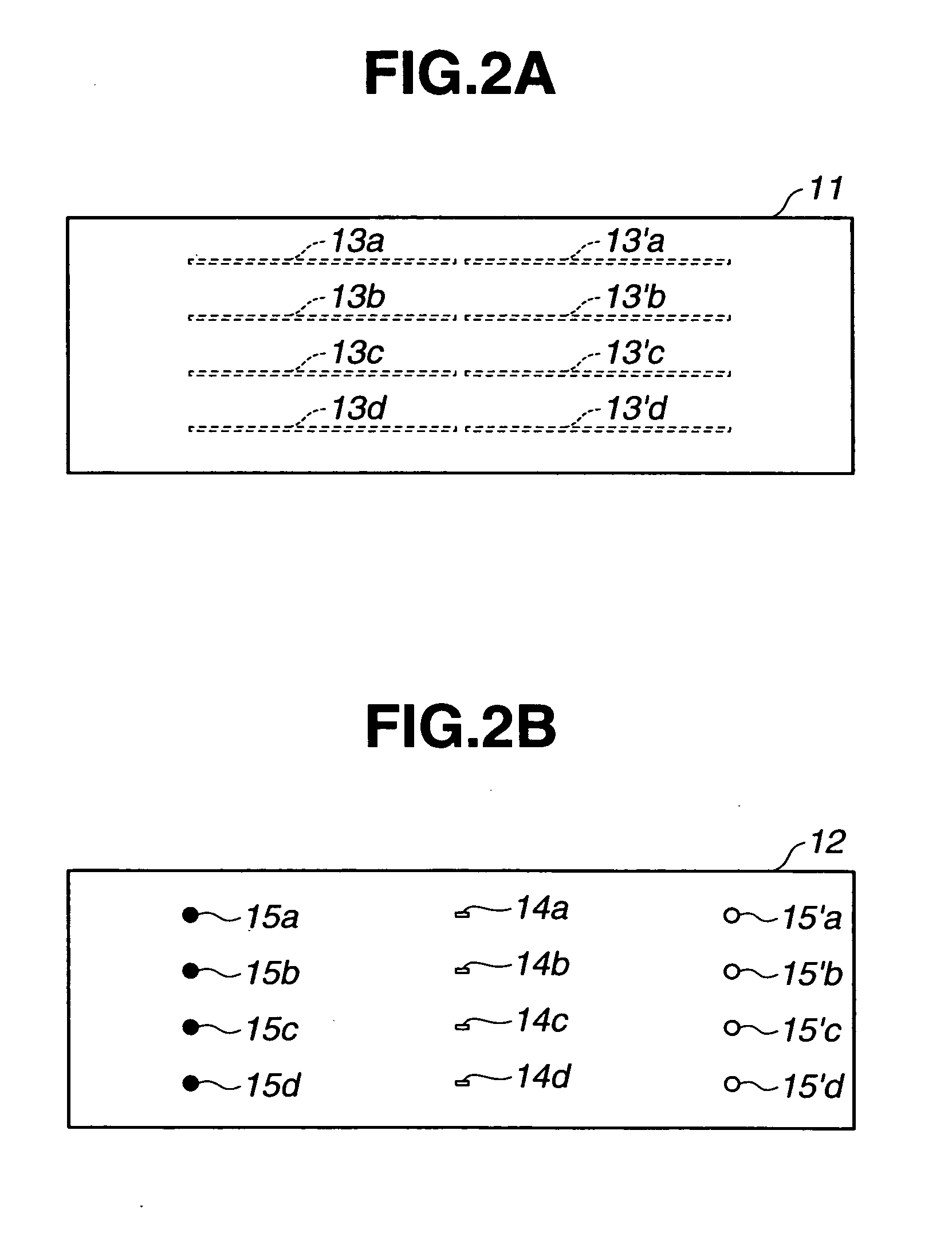
[0041] The microfluidic chip 10 includes two plates 11 and 12, each having a gr...


PUM


Abstract

A microfluidic system includes a plate-shaped microfluidic chip having a flow path, a liquid introduction tube for supplying liquid to the flow path, the liquid introduction tube having an end communicating with an end of the flow path and its other end that can be soaked in the liquid that is to be supplied to the flow path, and a liquid discharge head communicating with the other end of the flow path for discharging liquid that has passed through the flow path.

Description

BACKGROUND [0001] 1. Technical Field [0002] The present invention relates to a microfluidic system, sample analysis device, and target substance detection / measurement method used mainly for detecting reaction of a biological sample. [0003] 2. Related Art [0004] A method for performing chemical analysis, chemical synthesis, or biotechnology-related analysis by using a microfluidic chip composed of a glass plate having a fine flow path on its surface has been attracting attention. In a microfluidic chip, also called“micro total analytical system”(micro TAS), or“Lab-on-a chip,” etc., the required amount for a sample is smaller, the reaction time shorter, and the amount of waste smaller than in conventional devices. Because of those advantages, application in various fields, such as diagnosis, onsite analysis of environments or foods, is expected. [0005] Analysis using a microfluidic chip needs a means for stably introducing a sample solution to a fine flow path while controlling the in...

Claims


Application Information

Patent Timeline
Patent Type & Authority Applications(United States)
IPC IPC(8): B41J2/175
CPCB01L3/0268B01L3/502715B01L3/502746B01L3/563Y10T436/2575B01L2300/0816B01L2400/027B01L2400/0439B01L2400/0487B01L2200/027
Inventor TAKAGI, FUMIO
Owner SEIKO EPSON CORP
Why Eureka
Try Eureka