
Microfluidic system, sample analysis device, and target substance detection/measurement method
a microfluidic system and sample analysis technology, applied in the direction of fluid speed measurement, optical light guide, material analysis, etc., can solve the problems of large apparatus, insufficient utilization of the compact structure of the microfluidic system, and delay in reaction time and sample solution, etc., to achieve stable introduction and small dead volume
- Summary
- Abstract
- Description
- Claims
- Application Information
AI Technical Summary
Benefits of technology
Problems solved by technology
Method used
Image

Examples
Embodiment Construction
[0039]Preferred embodiments of the present invention will be described below with reference to the drawings.
Microfluidic System and Microfluidic Chip
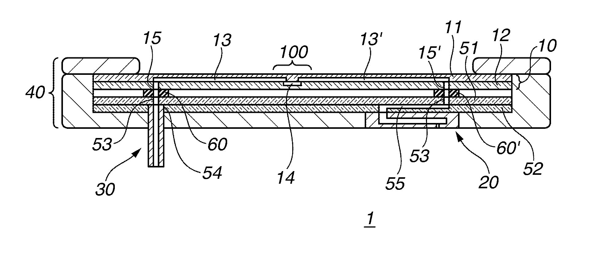
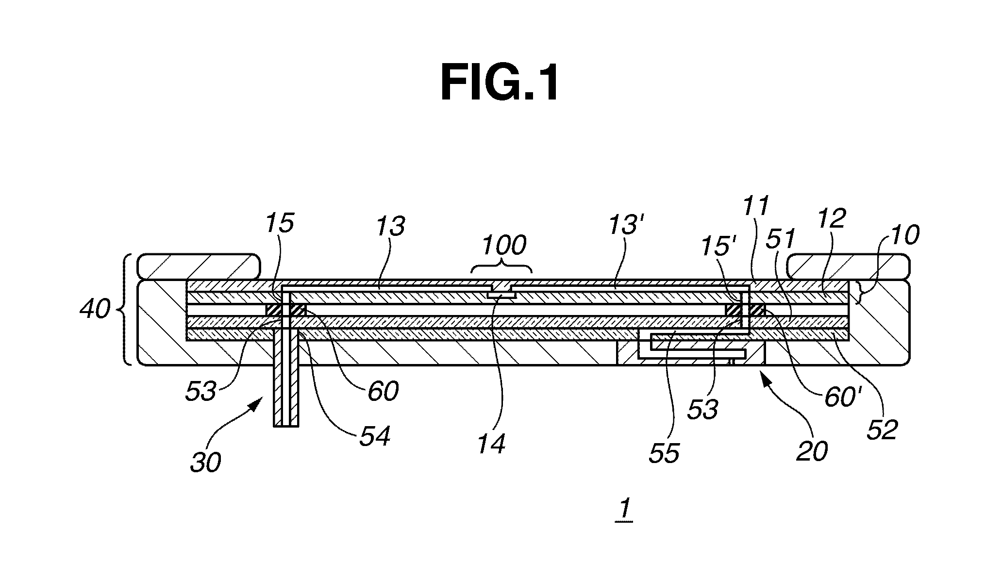
[0040]FIG. 1 shows the schematic cross sectional view of a microfluidic system 1 according to an aspect of the present invention.
[0041]The microfluidic system 1 includes a plate-shaped microfluidic chip 10 having continuous flow paths 13, 14, and 13′, a cylindrical liquid introduction tube 30 connected to an end of the flow path 13 for supplying liquid to the flow paths 13, 14, and 13′, and a liquid discharge head 20 connected to an end of the flow path 13′ for discharging the liquid that has passed through the flow paths 13, 14, and 13′.
[0042]The microfluidic system 1 is held by a holder 40, to which the plates 51 and 52 having the flow paths are fixed. The liquid discharge head 20 and the liquid introduction tube 30 are also fixed to the holder 40.
[0043]The microfluidic chip 10 includes two plates 11 and 12, each having a groove used ...
PUM
| Property | Measurement | Unit |
|---|---|---|
| depth | aaaaa | aaaaa |
| depth | aaaaa | aaaaa |
| diameter | aaaaa | aaaaa |
Abstract
Description
Claims
Application Information