Co2 refrigeration system

a refrigeration system and co2 technology, applied in water skiing, sports equipment, ski bindings, etc., can solve the problems of high flammability of refrigerants and represent a risk to local safety

Active Publication Date: 2015-12-10
TOROMONT INDS
View PDF12 Cites 14 Cited by
  • Summary
  • Abstract
  • Description
  • Claims
  • Application Information

AI Technical Summary

Problems solved by technology

Although ammonia and hydrocarbons have negligible ozone-depletion potential and global-warming potential as does CO2, these refrigerants are highly flammable and therefore represent a risk to local safety.

Method used


Image

  • Co2 refrigeration system
  • Co2 refrigeration system
  • Co2 refrigeration system

Examples


Embodiment Construction

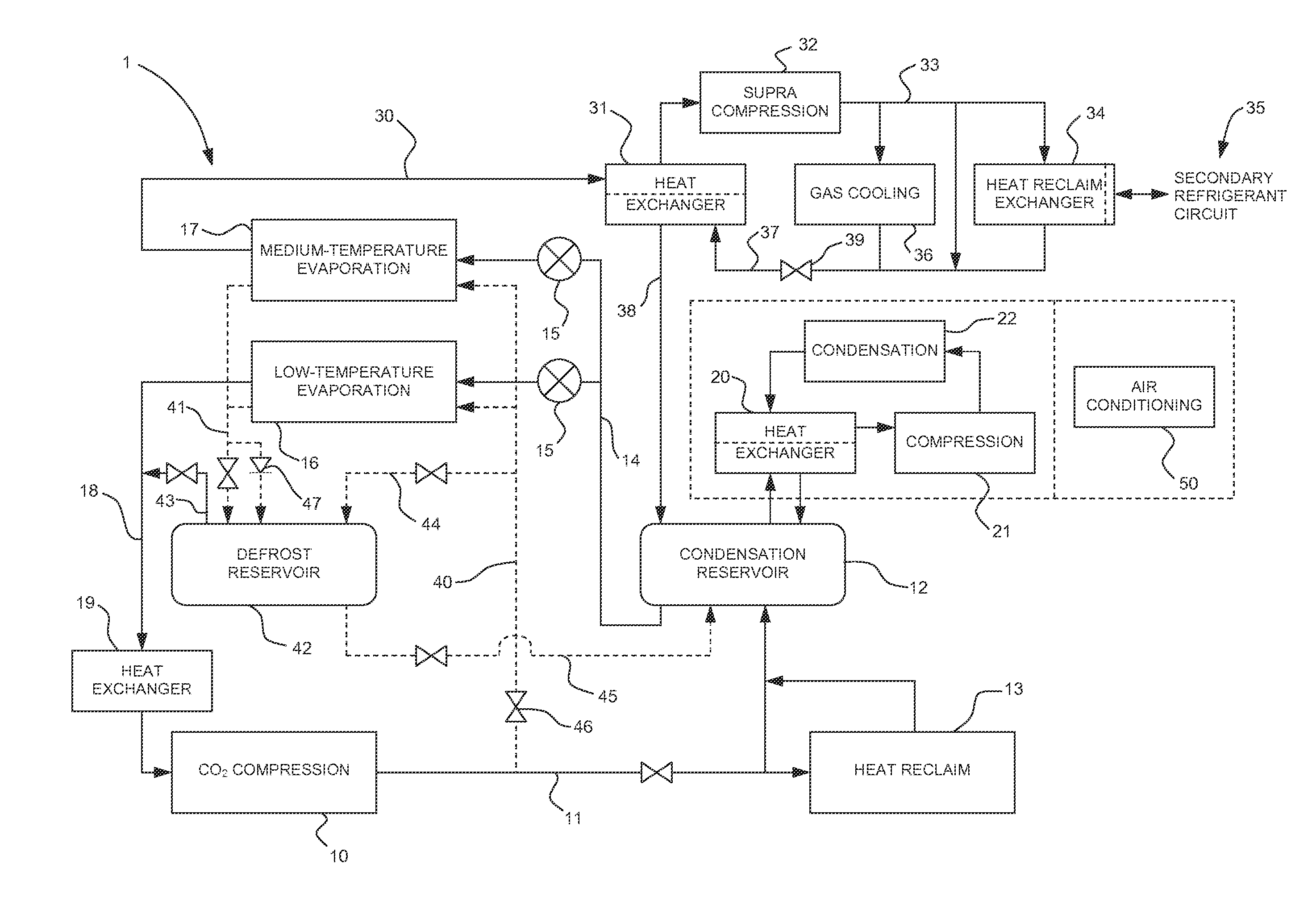
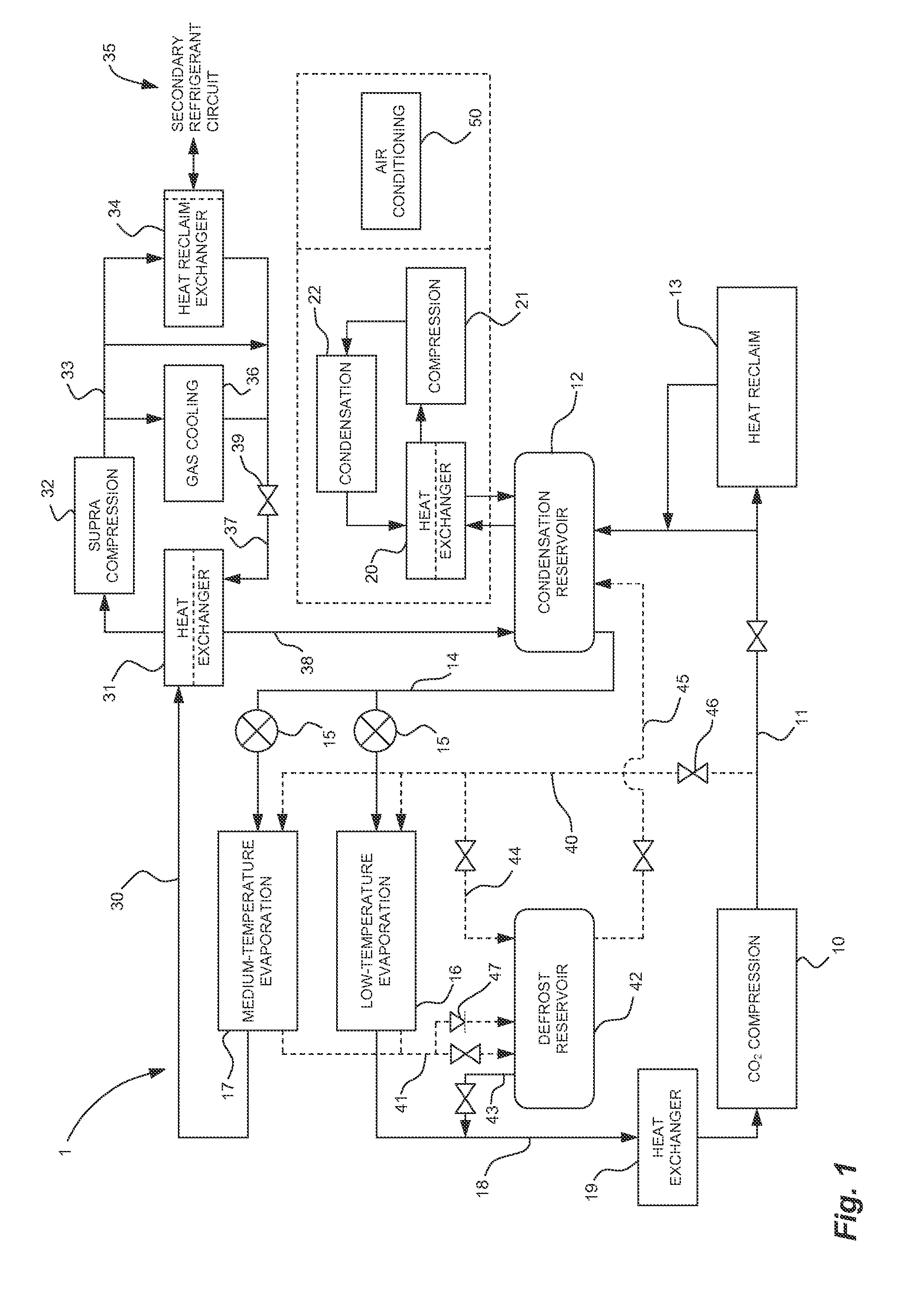
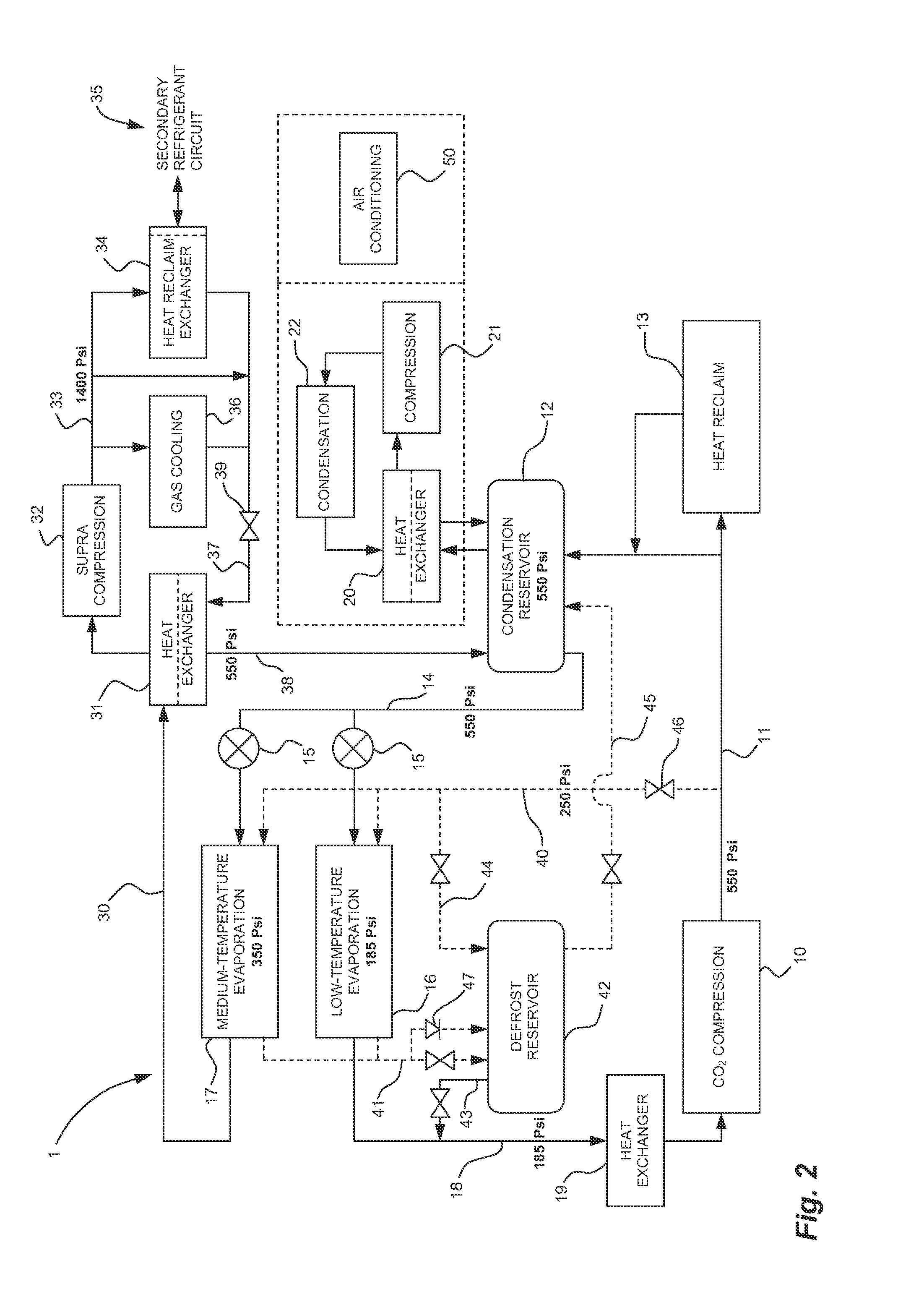
[0034]Referring to FIG. 1, a CO2 refrigeration system in accordance with an embodiment is illustrated at 1. The CO2 refrigeration system 1 has a CO2 refrigeration circuit comprising a CO2 compression stage 10. CO2 refrigerant is compressed in the compression stage 10, and is subsequently directed via line 11 to a condensation reservoir 12, or to a heat-reclaim stage 13.

[0035]The condensation reservoir 12 accumulates CO2 refrigerant in a liquid and gaseous state, and is in a heat-exchange relation with a condensation circuit that absorbs heat from the CO2 refrigerant. The condensation circuit is described in further detail hereinafter. Moreover, a transcritical circuit and a defrost circuit may supply CO2 refrigerant to the condensation reservoir 12, as is described in further detail hereinafter.

[0036]The heat-reclaim stage 13 is provided to absorb heat from the CO2 refrigerant exiting from the compression stage 10. The heat-reclaim stage 13 may take various forms, such as that of a ...


PUM


Abstract

A CO2 refrigeration system for an ice-playing surface, comprising: a compression portion comprising a compression stage comprising at least one compressor in which CO2 refrigerant is compressed to a transcritical state. A gas cooling stage in which the CO2 refrigerant compressed to the transcritical state releases heat by heat exchange with a gas. Pressure-regulating means downstream of the gas cooling stage control a pressure of the CO2 refrigerant in the compression portion of the CO2 refrigeration system. An oil circuit is in the CO2 refrigeration system, the oil circuit collecting oil downstream of the at least one compressor in the compression stage, the oil circuit directing the oil upstream of the at least one compressor for the CO2 refrigerant fed to the compressor to have an oil content.

Description

CROSS-REFERENCE TO RELATED APPLICATION[0001]The present application is a continuation of U.S. patent application Ser. No. 13 / 124,894, which is a national phase entry of PCT / CA09 / 01536, filed on Oct. 23, 2008, which claims priority on U.S. Patent Application No. 61 / 107,689, filed on Oct. 23, 2008, No. 61 / 166,884, filed on Apr. 6, 2009, and No. 61 / 184,021, filed on Jun. 4, 2009.FIELD OF THE APPLICATION[0002]The present application relates to refrigeration systems, and more particularly to refrigeration systems using CO2 refrigerant.BACKGROUND OF THE ART[0003]With the growing concern for global warming, the use of chlorofluorocarbons (CFCs) and hydrochlorofluorocarbons (HCFCs) as refrigerant has been identified as having a negative impact on the environment. These chemicals have non-negligible ozone-depletion potential and / or global-warming potential.[0004]As alternatives to CFCs and HCFCs, ammonia, hydrocarbons and CO2 are used as refrigerants. Although ammonia and hydrocarbons have n...

Claims


Application Information

Patent Timeline
Patent Type & Authority Applications(United States)
IPC IPC(8): F25C3/02F25B5/02F25B31/00F25B9/00
CPCF25C3/02F25B9/008F25B5/02F25B2309/061F25B31/004F25B2309/06F25B31/00F24F3/1417F24F2003/144F25B29/003
Inventor DUBE, SERGE
Owner TOROMONT INDS
Why Eureka
Try Eureka