
Toner

a technology of toner and spherical paper, which is applied in the field of toner, can solve the problems of reducing the heat quantity required in the fixing device, the impact of energy saving, and the decrease of the thermal storage resistance, and achieves excellent thermal storage resistance and long-term storage stability, excellent sharp melting properties, and low temperature fixability

Inactive Publication Date: 2015-12-10
CANON KK
View PDF4 Cites 7 Cited by
  • Summary
  • Abstract
  • Description
  • Claims
  • Application Information

AI Technical Summary

Benefits of technology

The patent text describes a new type of toner that has several advantages. Firstly, it has a sharp melting property, meaning it melts quickly when heated. Secondly, it is easy to fix at low temperatures. Thirdly, it is resistant to thermal damage and can be stored for long periods of time without losing its effectiveness.

Problems solved by technology

In recent years, energy saving has been regarded as a significant technical issue even in electrophotographic apparatuses, and major reduction in the heat quantity required in fixing devices has been examined.
However, since a decrease in Tg leads to a decrease in the thermal storage resistance of toners, it is difficult to achieve both the low-temperature fixability and thermal storage resistance of toners by this method.
However, this technology has a problem in that fixation in a lower temperature range cannot be achieved because the crystalline polyester has a high melting point.
Therefore, the sharp-melting property of the crystalline polyester cannot be sufficiently utilized.
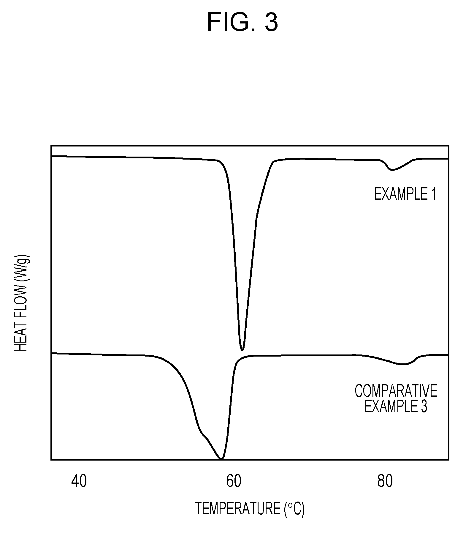
However, according to the examination conducted by the inventors of the present invention on the basis of the disclosures above, it was found that the melting point peak of the crystalline polyester in a toner was broad and thus the sharp-melting property of the crystalline polyester could not be effectively utilized.
As described above, there is still a problem before achieving both low-temperature fixability and thermal storage resistance.

Method used


Image

  • Toner
  • Toner
  • Toner

Examples


example 1

Production of Toner Particles (Before Treatment)

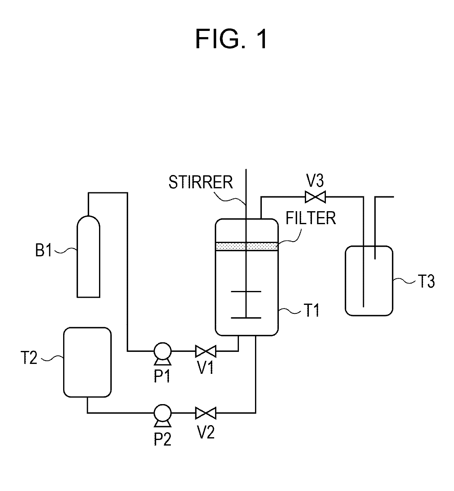
[0220]In the experimental apparatus shown in FIG. 1, valves V1 and V2 and a pressure-controlling valve 3 were closed. The resin fine particle dispersion liquid 1 was put into a pressure-resistant granulation tank T1 including a stirring mechanism and a filter for filtering toner particles. The internal temperature was adjusted to 30° C. Subsequently, the valve V1 was opened to introduce carbon dioxide (purity: 99.99%) to the pressure-resistant granulation tank T1 from a cylinder B1 using a pump P1. When the internal pressure reached 5 MPa, the valve V1 was closed.

[0221]The block polymer resin solution 1, the wax dispersion liquid 1, the coloring agent dispersion liquid 1, and acetone were put into a resin solution tank T2, and the internal temperature was adjusted to 30° C.

[0222]The valve V2 was then opened to introduce the contents of the resin solution tank T2 to the granulation tank T1 using a pump P2 while the inside of the granula...

examples 2 to 17 and 19

[0242]Toners 2 to 17 and 19 were produced in the same manner as in Example 1, except that the types of resins used and the annealing conditions were changed to those shown in Table 4. Table 5 shows the physical properties of the resultant toners. Table 6 shows the results of the same evaluation as that conducted in Example 1.

[0243]In the endothermic curve of the toners 5 and 9, the maximum endothermic peak overlapped the endothermic peak derived from the wax. Therefore, in the analysis, the endothermic amount derived from the wax was subtracted from the maximum endothermic peak.

example 18

[0244]Toner particles (before treatment) 18 were produced in the same manner as in Example 1, except that the amount of each component in the production process of the toner particles (before treatment) 1 was changed to be as follows.

crystalline polyester resin solution 1112.0 parts by mass amorphous resin solution 148.0 parts by masswax dispersion liquid 162.5 parts by masscoloring agent dispersion liquid 125.0 parts by massacetone35.0 parts by massresin fine particle dispersion liquid 125.0 parts by masscarbon dioxide320.0 parts by mass

[0245]The resultant toner particles (before treatment) 18 were subjected to DSC measurement. The peak temperature of the maximum endothermic peak was 65° C.

[0246]A toner 18 was produced by performing an annealing treatment on the resultant toner particles (before treatment) 18 in the same manner as in Example 1, except that the annealing temperature was changed to 58° C.

[0247]Table 5 shows the physical properties of the resultant toner. Table 6 sho...


PUM

PropertyMeasurementUnit
endothermic peak temperatureaaaaaaaaaa

Abstract

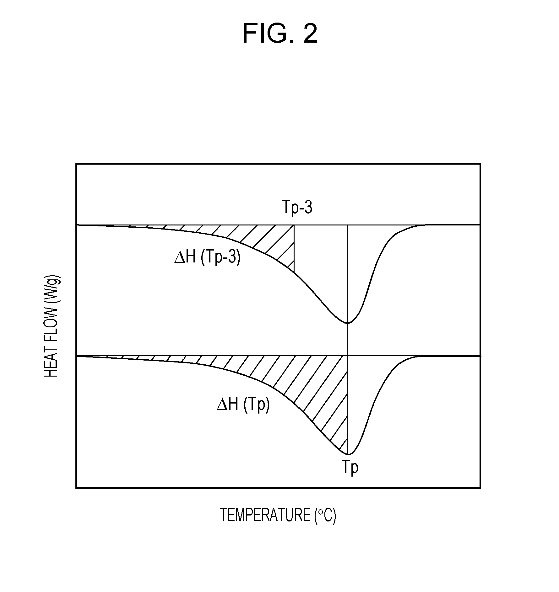
In the measurement of an endothermic amount of a toner, (1) an endothermic peak temperature (Tp) derived from the binder resin is 50° C. or higher and 80° C. or lower; (2) a total endothermic amount (ΔH) derived from the binder resin is 30 [J / g] or more and 125 [J / g] or less based on mass of the binder resin; (3) when an endothermic amount derived from the binder resin from an initiation temperature of an endothermic process to Tp is represented by ΔHTp [J / g], ΔH and ΔHTp satisfy formula (1) below; and (4) when an endothermic amount derived from the binder resin from the initiation temperature of an endothermic process to a temperature 3.0° C. lower than Tp is represented by ΔHTp-3 [J / g], ΔH and ΔHTp-3 satisfy formula (2) below.0.30≦ΔHTp / ΔH≦0.50  (1)0.00≦ΔHTp-3 / ΔH≦0.20  (2)

Description

CROSS REFERENCE TO RELATED APPLICATIONS[0001]This application is a Divisional of U.S. patent application Ser. No. 13 / 811,241 filed Jan. 18, 2013, and which was a National Stage Entry of PCT / JP2011 / 066645 filed on Jul. 14, 2011, which claims priority to Japanese Patent Application No. 2010-165305 filed Jul. 22, 2010, all of which are hereby incorporated by reference herein in their entireties.TECHNICAL FIELD[0002]The present invention relates to a toner used in electrophotography, electrostatic recording, or toner jet recording.BACKGROUND ART[0003]In recent years, energy saving has been regarded as a significant technical issue even in electrophotographic apparatuses, and major reduction in the heat quantity required in fixing devices has been examined. Thus, a toner having so-called “low-temperature fixability” that allows fixation with lower energy has been increasingly demanded.[0004]A decrease in the glass transition temperature (Tg) of a binder resin in a toner is exemplified as...

Claims


Application Information

Patent Timeline
Patent Type & Authority Applications(United States)
IPC IPC(8): G03G9/087G03G9/08
CPCG03G9/0804G03G9/08755G03G9/08788G03G9/08795G03G9/08797
Inventor AOKI, KENJITANI, ATSUSHIKAYA, TAKAAKIOKAMOTO, AYAKOKASUYA, TAKASHIGE
Owner CANON KK
Learn More