System and Method for Heart Valve Anchoring

a heart valve and anchoring technology, applied in the field of system and method of percutaneous heart valve replacement, can solve the problems of limiting the benefits of the procedure, affecting the quality of life of patients,

Inactive Publication Date: 2015-12-17
MICRO INTERVENTIONAL DEVICES
View PDF5 Cites 3 Cited by
  • Summary
  • Abstract
  • Description
  • Claims
  • Application Information

AI Technical Summary

Benefits of technology

[0012]The system of the present invention may include an applicator, including an applicator shaft passing through the ring, and terminating at its distal end in one or more spring arms. The spring arms may connect the distal end of the applicator shaft to the ring, such that the spring arms exert a spring force against the ring, pushing the ring radially outward. Each spring arm is separately connected to the ring, so that, in the case of a plurality of spring arms, each spring arm may each respond individually to an irregularly shaped implant site, allowing the ring to form to the shape of the implant site, and provide a better seat for the prosthetic heart valve.
[0015]In this manner, the prosthetic valve may be securely fixed to the implant site, to more sufficiently and effectively improve valve function. The prosthetic may take a variety of shapes. The shape of the prosthetic to be used for a particular application may be selected based on the particular geometric needs of the particular application.

Problems solved by technology

For example, percutaneous repair involves modified surgical techniques, which can limit the benefits of the procedure.
Annular rings may lack effectiveness, and include risks of erosion, perforation, and coronary artery thrombosis.
Edge-to-edge repair can be technically demanding, and may lack long term durability.
Depending upon the particular valve failure, combinations of different repair techniques may be necessary, further complicating the procedure and limiting its effectiveness.
Open surgery solutions for heart valve replacement, however, carry significant risks to the patient.
Moreover, fixing the heart valve implant to the implant site may be challenging, as the implant site may form an irregular shape, may lack calcium to secure the valve, or may cause difficulty in fixing the implant valve with the proper orientation.

Method used


Image

  • System and Method for Heart Valve Anchoring
  • System and Method for Heart Valve Anchoring
  • System and Method for Heart Valve Anchoring

Examples


Embodiment Construction

[0049]As set forth in greater detail below, example embodiments of the present invention allow for the reliable and effective delivery, implantation, and fixation of a heart valve replacement prosthetic, such that the prosthetic can effectively address heart valve failure.

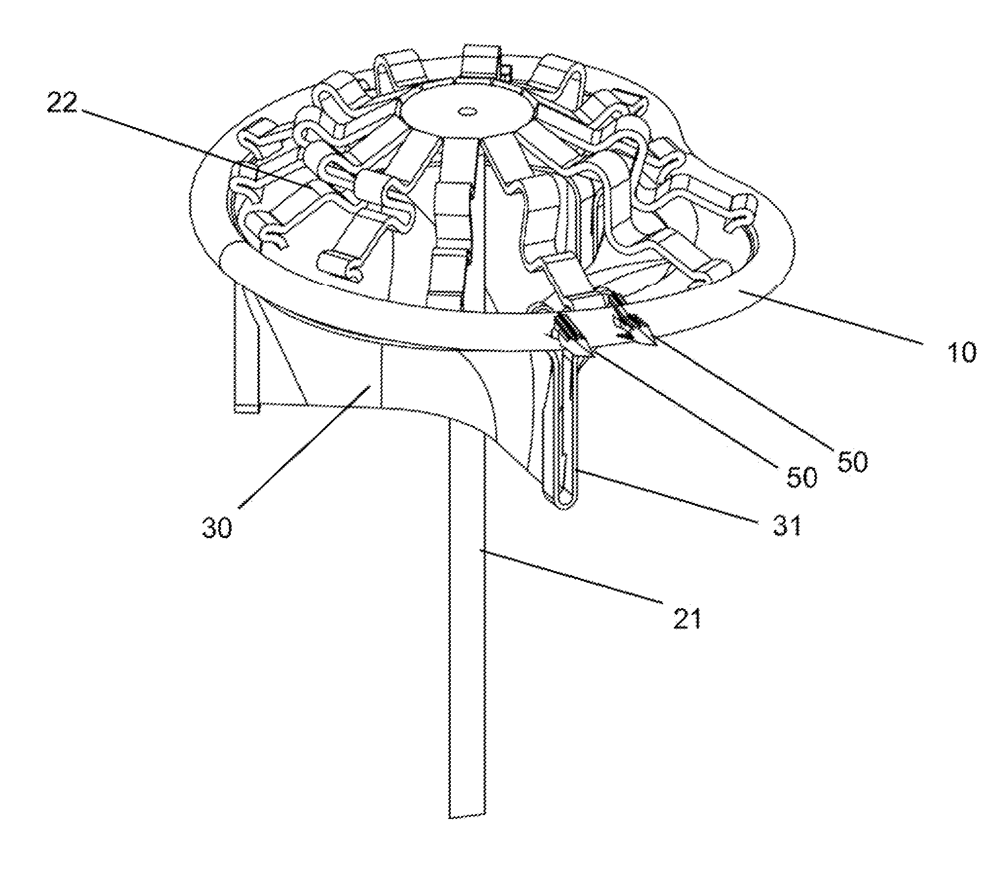
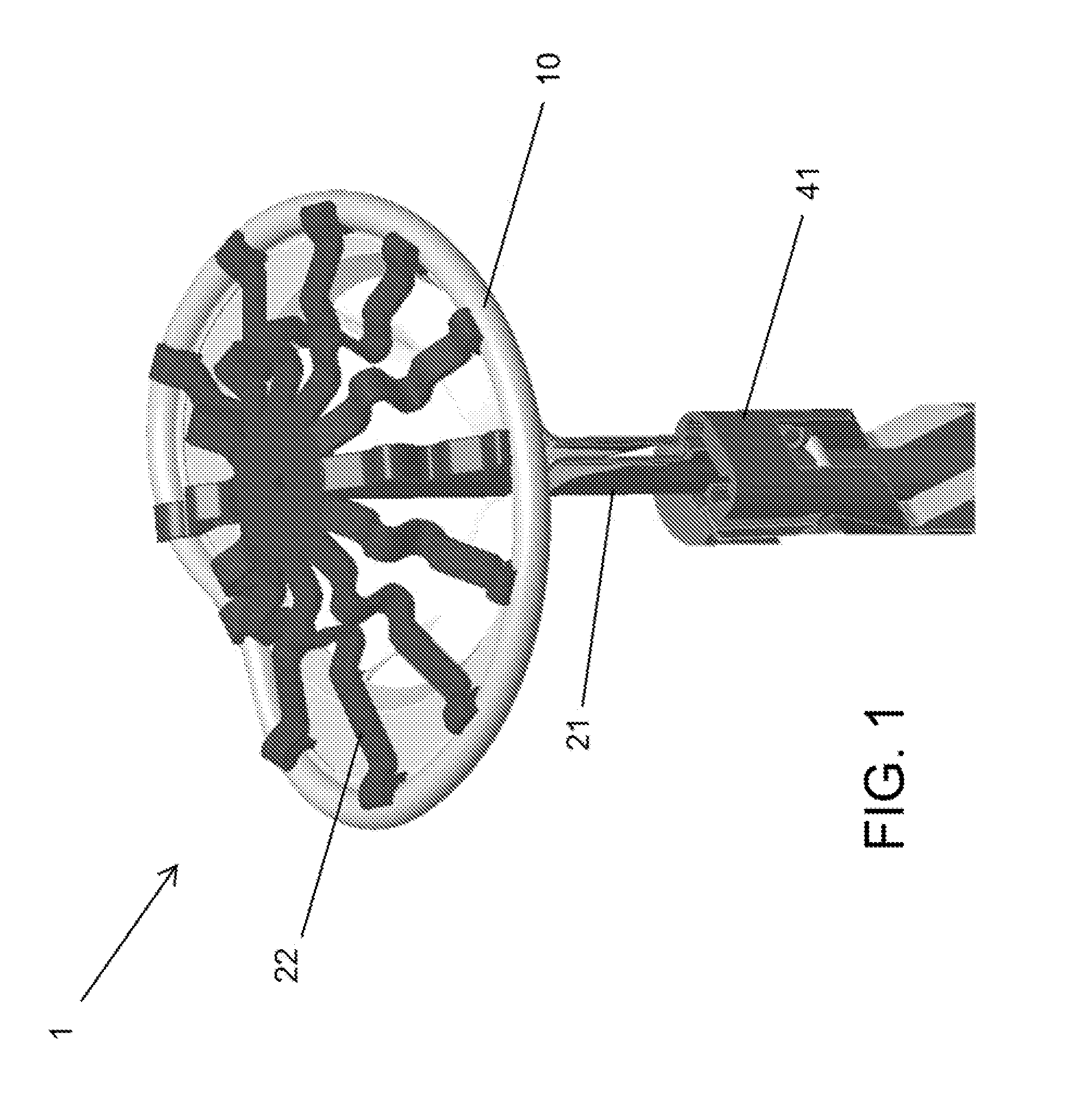
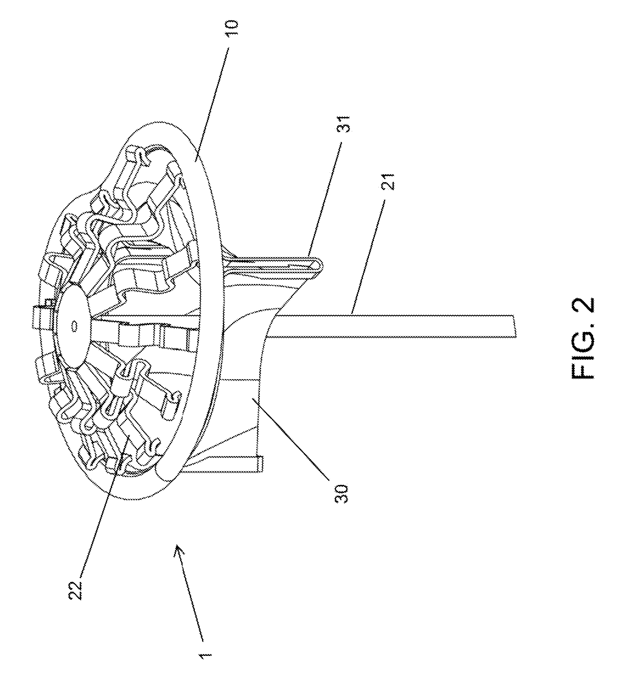
[0050]An exemplary embodiment of the present invention is present in FIG. 1. FIG. 1 illustrates heart valve replacement prosthetic 1 having ring 10, which, in an exemplary embodiment, may be elastic. FIG. 1 further illustrates applicator 20 having applicator shaft 21 and spring arms 22. Spring arms 22 may be affixed to the distal end of the applicator shaft 21, and may connect the distal end of the applicator shaft 21 to the ring 10 of the replacement prosthetic 1. FIG. 1 further illustrates driver 40, as will be described in more detail below.

[0051]As will be generally understood, as described by, for example, U.S. Pat. No. 7,621,948, the entirety of which is hereby incorporated by reference as if fully disclosed ...


PUM


Abstract

A system and method for percutaneous heart valve replacement includes implanting a heart valve replacement prosthetic into tissue and driving anchors into the heart valve replacement to affix the prosthetic to the tissue.

Description

CROSS-REFERENCE TO RELATED APPLICATIONS[0001]This application claims the benefit of, and incorporates by reference thereto in its entirety, U.S. Provisional Patent Application Ser. No. 62 / 010,680, filed on Jun. 11, 2014.[0002]Further, each of the following is hereby incorporated by reference thereto in its entirety: U.S. patent application Ser. No. 14 / 321,476, filed Jul. 1, 2014, U.S. patent application Ser. No. 14 / 301,106, filed Jun. 10, 2014, U.S. patent application Ser. No. 13 / 843,930, filed Mar. 15, 2013, PCT Application No. PCT / US14 / 30868, filed Mar. 17, 2014, U.S. patent application Ser. No. 13 / 010,769, filed Jan. 20, 2011, U.S. Provisional Patent Application Ser. No. 61 / 296,868, filed on Jan. 20, 2010, U.S. patent application Ser. No. 13 / 010,766, filed on Jan. 20, 2011, U.S. patent application Ser. No. 13 / 010,777, filed on Jan. 20, 2011, and U.S. patent application Ser. No. 13 / 010,774, filed on Jan. 20, 2011.FIELD OF THE INVENTION[0003]The present invention relates to a syste...

Claims


Application Information

Patent Timeline
Patent Type & Authority Applications(United States)
IPC IPC(8): A61F2/24
CPCA61F2/243A61F2/2427A61F2/2412A61F2/2409A61B17/068A61B2017/0647
Inventor WHITMAN, MICHAEL P.
Owner MICRO INTERVENTIONAL DEVICES
Why Eureka
Try Eureka