Securing Assembly

a technology for securing assemblies and assemblies, applied in the direction of load securing, load accommodation, transportation and packaging, etc., can solve the problems of object dislodged due to movement in transit, object if dislodged may break or be damaged, lashing methods and devices, etc., to reduce the amount of time and effort, the effect of reducing the chance of injury

Active Publication Date: 2015-12-17
123LASH PTE LTD
View PDF4 Cites 9 Cited by
  • Summary
  • Abstract
  • Description
  • Claims
  • Application Information

AI Technical Summary

Benefits of technology

[0011]Accordingly there is a need to greatly reduce the amount of time and effort required to load and unload objects from structures such as

Problems solved by technology

When such objects are being transported, in particular over long distances, the objects may become dislodged due to movement in transit.
The object if dislodged may break or be damaged which is undesirable.
There are however many problems with the existing lashing methods and devices.
Lashing workers are performing heavy, awkward work, frequently on an exposed, often slippery deck.
The environment is constantly changing, difficult to supervise and dangerous.
A delay between the time a ship arrives and the time of the first container being unloaded is an issue for ship owners.
This is often due to the time taken to unlash enough containers before the crane can start work safely to unload the containers.
The pressure to get containers unlashed therefore results in hurrying and frequently in injury and even death.
Lashing equipment is by its nature quite heavy.
This weight combined with a rods length and shape makes them awkward to handle.
This results in a process where the majority of the physical effort and time is related to handling lashing components.
This adds to the ship owners cost and while reducing the chance of strain through overloading a worker, adds to the risk of one worker striking another by accident in a space constrained deck.
By contrast in some ships the lashing is attached in such a way that the workers must lean across to handle the lashing, increasing the chance of back strain and also of losing balance and causing an accident.
In some ships this is done neatly in dedicated bins and racks, in others it results in bars being stored on walkways creating slip and trip hazards.
The deck environment and location is not conducive to good maintenance.
On many ships this results in poorly maintained bars (bent, rusted, worn etc).
Removal of a faulty component results in an awkward and physically arduous process to remove and replace the component.
The result of this is that faulty or suspect equipment remains in service when it should be removed for repair/replacement.
The high workload of attaching lashing means that ship owners and stevedores seek to use the minimum amount of lashing.
This in itself is not a problem but when extra lashing is required (e.g. bad weather expected) it results in a need to carry extra lashing up onto the deck (either up a ladder or even passing the bars around the outside of the ship) this is heavy and difficult work.
In some cases where conditions change it can result in the crew having to do this while at sea

Method used


Image

  • Securing Assembly
  • Securing Assembly
  • Securing Assembly

Examples


Embodiment Construction

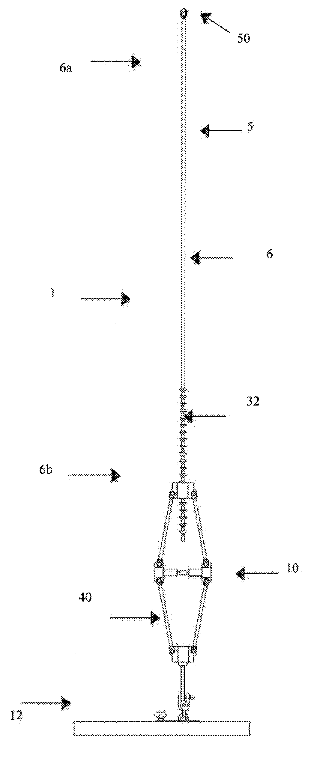
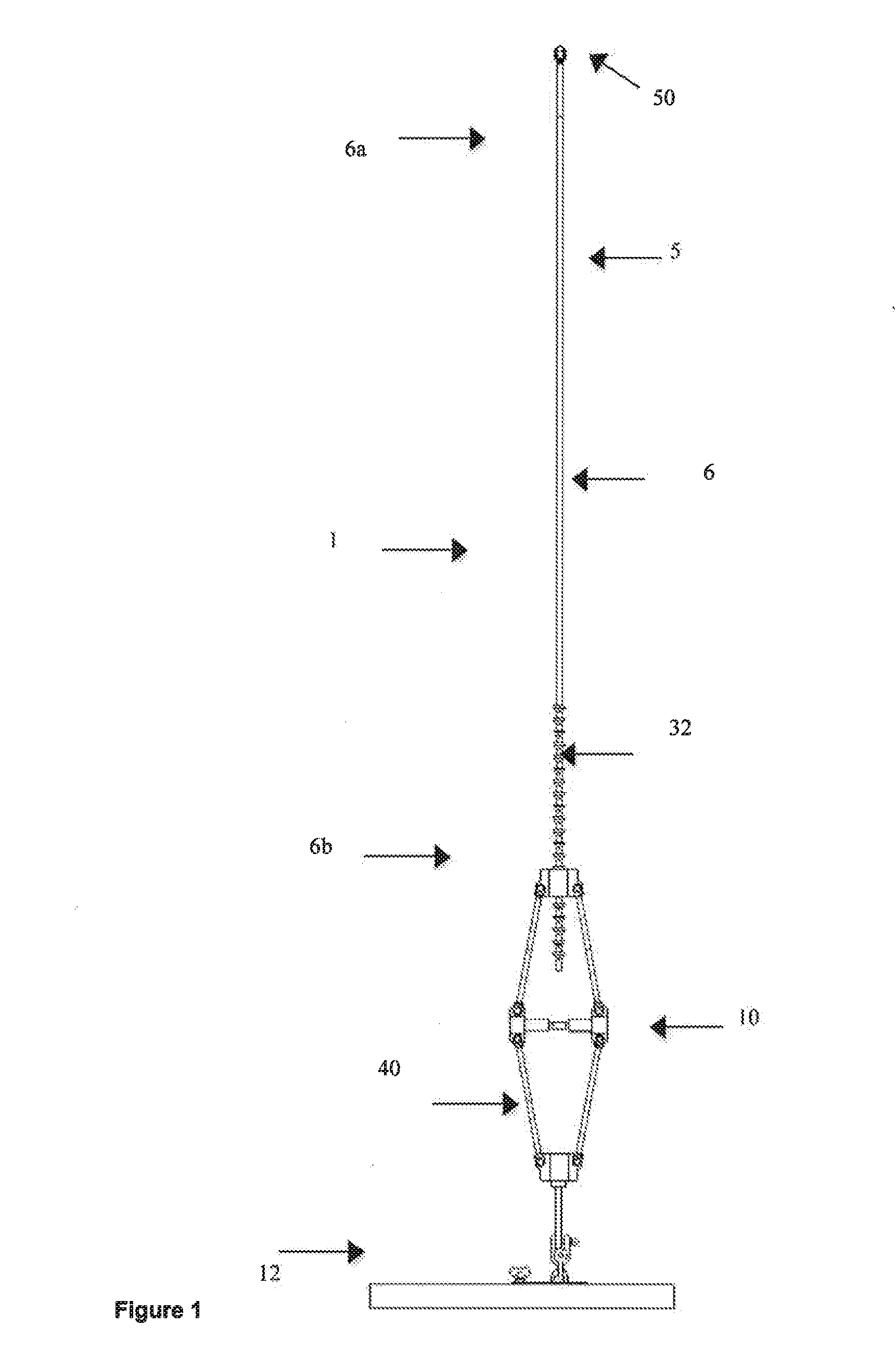
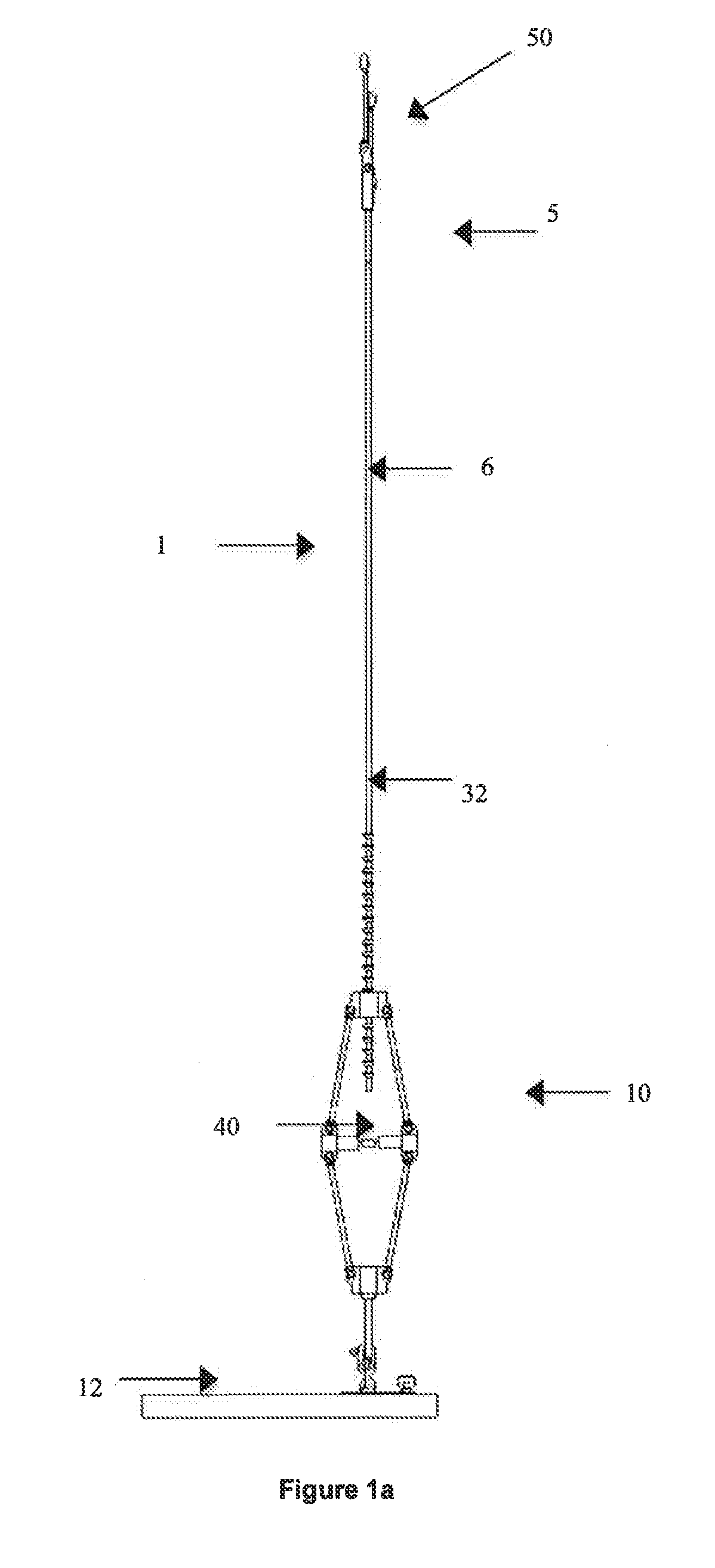
[0062]Referring to the figures there is disclosed an assembly 1 to secure objects 2 to a structure 3 such as a deck of a ship. The assembly 1 includes physical hardware and equipment for manipulating the hardware and processes for exploiting the equipment and hardware. The physical hardware consists of a lashing harness 1 that is designed to remain intact when transported, maintained and stored.

[0063]The assembly 1 includes attachment means 5 adapted to attach said assembly 1 to an object 2 in use. An elongate rod 6 has a first end 6a and a second end 6b. The first end 6a is connectable to the attachment means 5. The second end 6b is connectable to an adjustment means 10. A base 12 is adapted to connect said adjustment means 10 to said structure 3 in use. The adjustment means 10 is operable to adjust a tension between said object 2 and said structure 3 by way of said assembly 1 to secure said object 2 to said structure 3 in use. The base 12 as best seen in FIG. 7 includes a slide me...


PUM


Abstract

A securing assembly (1) adapted to secure objects (2) to a structure (3). The assembly (1) includes attachment means (5) adapted to attach said assembly to an object in use. An elongate rod (6) having a first end (6a) and a second end (6b). The first end connectable to the attachment means. The second end connectable to an adjustment means (5). A base (12) is adapted to connect said adjustment means to said structure in use. Whereby said adjustment means is operable to adjust a tension between said object and said structure by way of said assembly to secure said object to said structure in use.

Description

FIELD OF THE INVENTION[0001]The present invention relates to a securing assembly and in particular to an assembly to secure objects to a structure.BACKGROUND OF THE INVENTION[0002]Thousands of objects are transported around the world every day. Most such objects are packaged before transport and grouped together to form larger objects to be placed on or in pallets, shipping containers or the like. Those larger objects are then transported from one place to another by moving means such as planes, trains, trucks, ships or the like. When such objects are being transported, in particular over long distances, the objects may become dislodged due to movement in transit. The object if dislodged may break or be damaged which is undesirable. Accordingly, it has become necessary to secure the objects to a fixed structure, such as the deck of a ship, flatbed of a truck or the like, during transit.[0003]Referring particulary, but not exclusively to shipping, it is common to transport objects in...

Claims


Application Information

Patent Timeline
IPC IPC(8): B60P7/08B63B25/28
CPCB63B25/28B60P7/08B63B2025/285B60P7/13B63B25/00B65D88/12B65D88/121B61D3/20B65D88/129B63B25/004B60P7/18B61D45/007B60P7/10B63B25/002
Inventor BEAN, DAVID ROBIN
Owner 123LASH PTE LTD
Why Eureka
Try Eureka