External load mass rope of a rotorcraft
a technology of external load and rope, which is applied in the direction of launch weapons, fuselages, transportation and packaging, etc., can solve the problems of affecting the performance of the cable that implements the single rope, the limiting factor of the maximum external load of the cargo hook, and the inability to use the cable with the cargo hook devi
- Summary
- Abstract
- Description
- Claims
- Application Information
AI Technical Summary
Benefits of technology
Problems solved by technology
Method used
Image
Examples
first embodiment
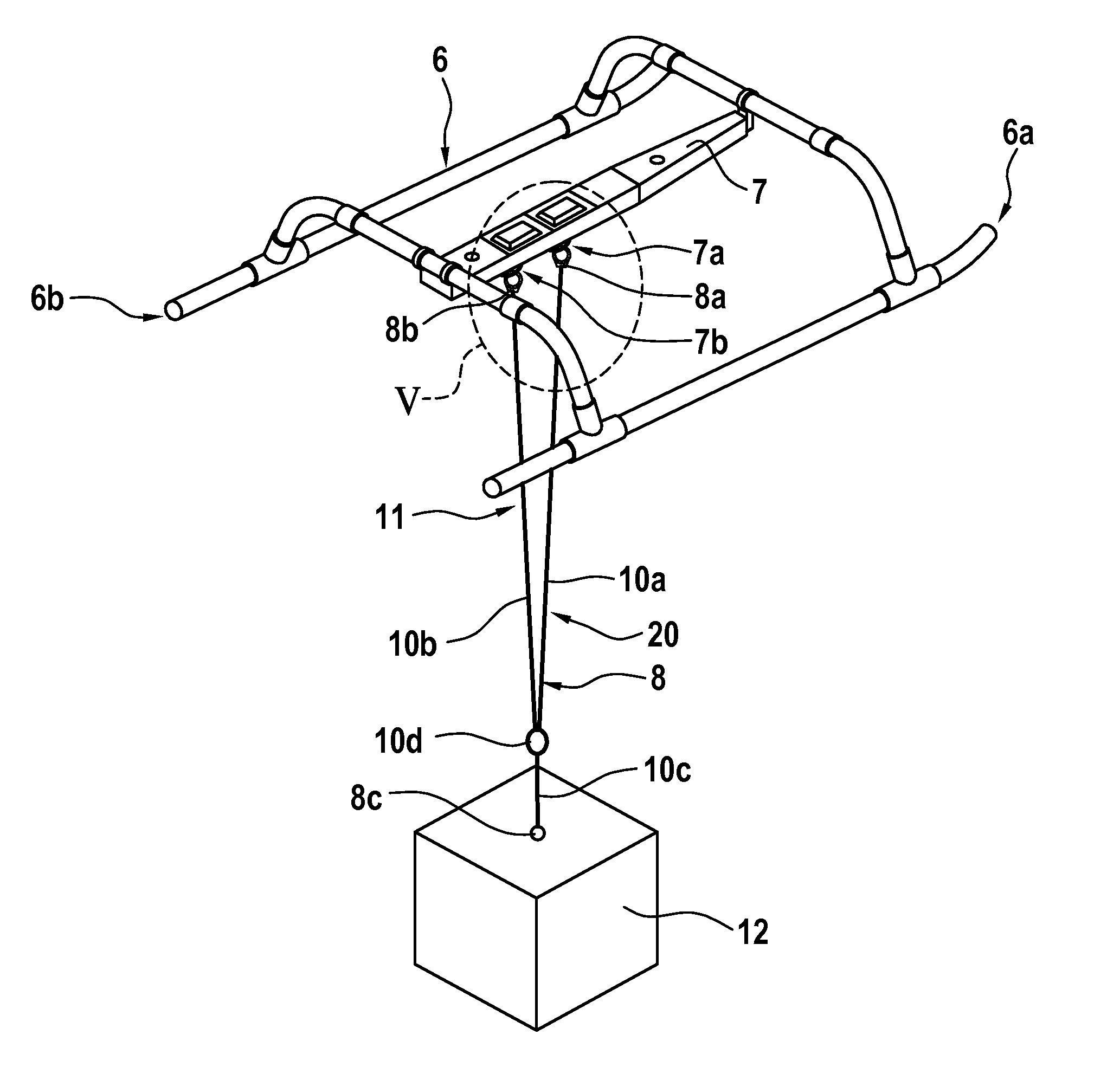
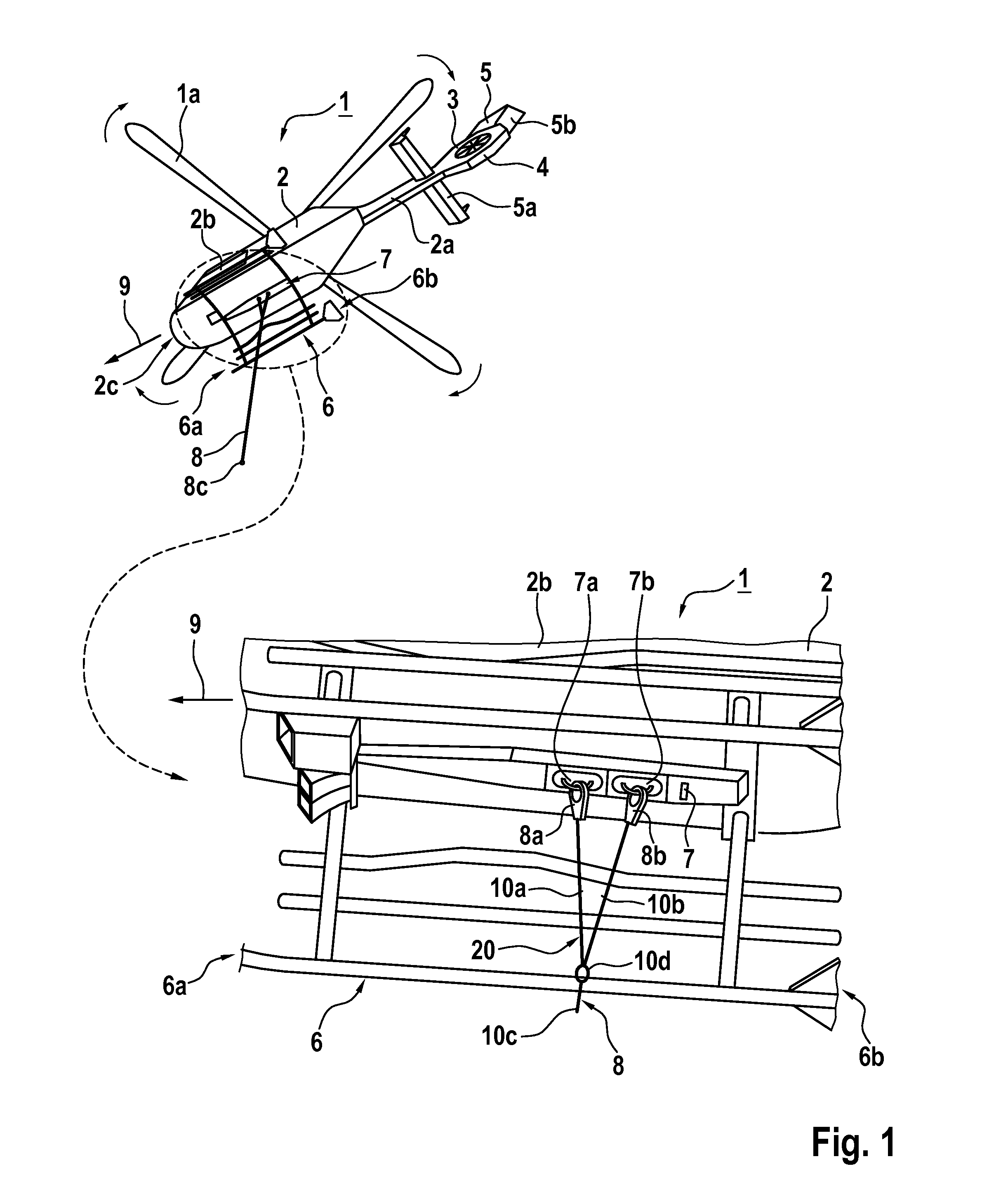
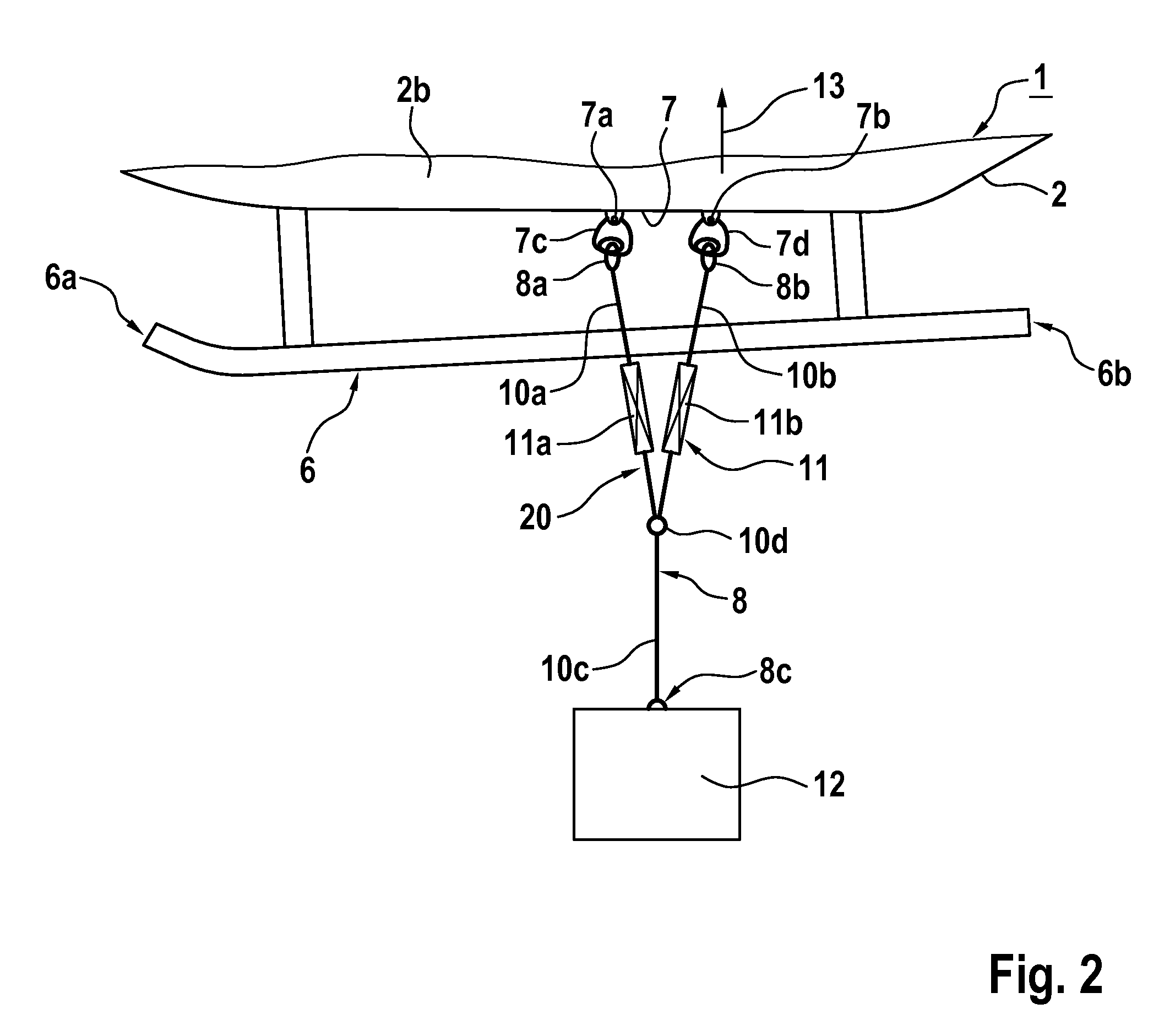
[0080]FIG. 4 shows the landing gear 6 of the helicopter 1 of FIG. 1 and FIG. 2, which is by way of example represented in hover of the helicopter 1. As described at FIG. 2, the landing gear 6 has the cargo hook device 7 attached thereto and to the Y-rope 8, which in turn is attached to the external load mass 12. The Y-rope 8 and, more specifically, the V-rope 20 comprises the length adjustment device 11, which is embodied that is described in more detail below at FIG. 7 with a rope material having predefined lengthening properties for elastic elongation, such as polyamide.
[0081]FIG. 5 shows the cargo hook attachment points 7a, 7b of the cargo hook device 7 of FIG. 4 in greater detail, which are provided with the cargo hooks 7c, 7d, respectively. Furthermore, the attachment rings 8a, 8b of the forward and aft legs 10a, 10b of the V-rope 20 of FIG. 4, which are attached to the cargo hooks 7c, 7d, respectively, are also shown in greater detail.
[0082]FIG. 6 shows an exemplary character...
second embodiment
[0096]FIG. 9 shows the landing gear 6 of the helicopter 1 of FIG. 1 and FIG. 2, which is by way of example represented in hover of the helicopter 1 according to FIG. 7 with the cargo hook device 7 that is attached to the landing gear 6 and to the Y-rope 8, which in turn is attached to the external load mass 12. However, in contrast to FIG. 7, the V-rope 20 is now formed in one piece, i.e. without being separated into two parts by the leg interface 10d. Furthermore, the length adjustment device 11 of the Y-rope 8 and, more specifically, of the V-rope 20 is now embodied with a guide pulley arrangement 22 instead of the rope material having the predefined lengthening properties for elastic elongation. The guide pulley arrangement 22 is described in more detail below with reference to FIG. 10.
[0097]FIG. 10 shows according to FIG. 9 the landing gear 6 with the cargo hook device 7 that is attached to the latter and to the Y-rope 8, which in turn is attached to the external load mass 12, ...
third embodiment
[0100]FIG. 11 shows the landing gear 6 of the helicopter 1 of FIG. 1 and FIG. 2, which is by way of example represented in hover of the helicopter 1 according to FIG. 7 with the cargo hook device 7 that is attached to the landing gear 6 and to the Y-rope 8, which in turn is attached to the external load mass 12. However, in contrast to FIG. 7, the length adjustment device 11 of the Y-rope 8 and, more specifically, of the V-rope 20 is now embodied with at least one spring coil damper 23a, 23b having predefined dampening properties, instead of the rope material having the predefined lengthening properties for elastic elongation.
[0101]Preferably, each one of the length adjustment units 11a, 11b of the length adjustment device 11 is embodied according to the third embodiment, i.e. with at least one spring coil damper 23a, 23b having predefined dampening properties. Illustratively, the length adjustment unit 11a of the forward leg 10a of the V-rope 20 has a spring coil damper 23a and th...
PUM
 Abstract
Description
Claims
Application Information
 - R&D
- Intellectual Property
- Life Sciences
- Materials
- Tech Scout
- Unparalleled Data Quality
- Higher Quality Content
- 60% Fewer Hallucinations
Browse by: Latest US Patents, China's latest patents, Technical Efficacy Thesaurus, Application Domain, Technology Topic, Popular Technical Reports.
© 2025 PatSnap. All rights reserved.Legal|Privacy policy|Modern Slavery Act Transparency Statement|Sitemap|About US| Contact US: help@patsnap.com


