
Dismantlable self-assembly structure

Active Publication Date: 2015-12-17
AVANTPACK
View PDF25 Cites 2 Cited by
  • Summary
  • Abstract
  • Description
  • Claims
  • Application Information

AI Technical Summary

Benefits of technology

The invention describes a pallet that does not require additional elements to secure its unions, which is beneficial for recycling purposes. The cross members on the pallet have a wide width to provide a large support surface for the goods placed on it, and the sides of the cross members are flush with the ends of the longitudinal members, preventing protrusions that may hinder handling and storage of assembled pallets.

Problems solved by technology

In long-distance hauls the cost of returning the pallets due to their bulk makes the recovery thereof uneconomical.
It is also not easy to sell new pallets to distant locations as the trip between the manufacturer and the first user is also performed without a load.
Dismantlable pallets also favour the replacement of broken parts, as in non-dismantlable pellets a broken part often makes the pallet unusable, with the ensuing economic and environment cost.
This solution presents some manufacturing drawbacks mainly resulting from the protrusions that must be attached to the slat at a later stage, as well as transportation problems as the protrusions prevent optimising space in the transport when the pallet is transported dismantled.
Utility model ES1077901U relates to a self-assembly pallet configured on the basis of a horizontal platform provided with tab-like incuts such that these tabs must be able to deform in order to assume a vertical position, thereby limiting the materials that can be used with this technical solution.
In addition, the assemblies produce protrusions in the structure that hinder the handling and storage thereof.
The assembly thus obtained produces protrusions that hinder the storage and handling of the pallet.
This patent requires several different parts and rods and due to the union method protrusions are created that hinder the handling and storage of the pallet.

Method used


Image

  • Dismantlable self-assembly structure
  • Dismantlable self-assembly structure
  • Dismantlable self-assembly structure

Examples


Embodiment Construction

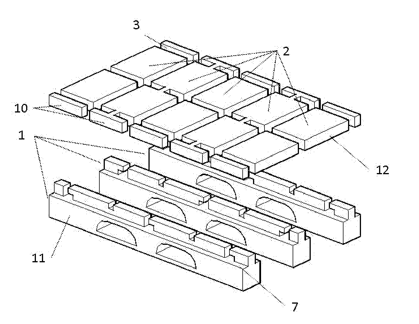
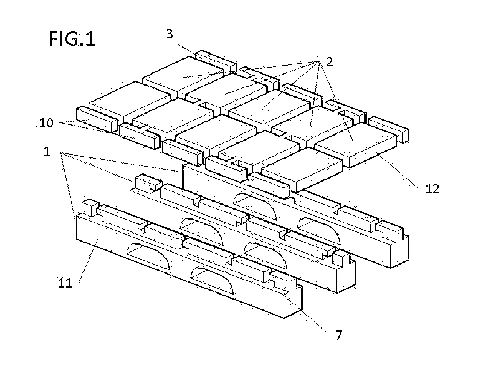
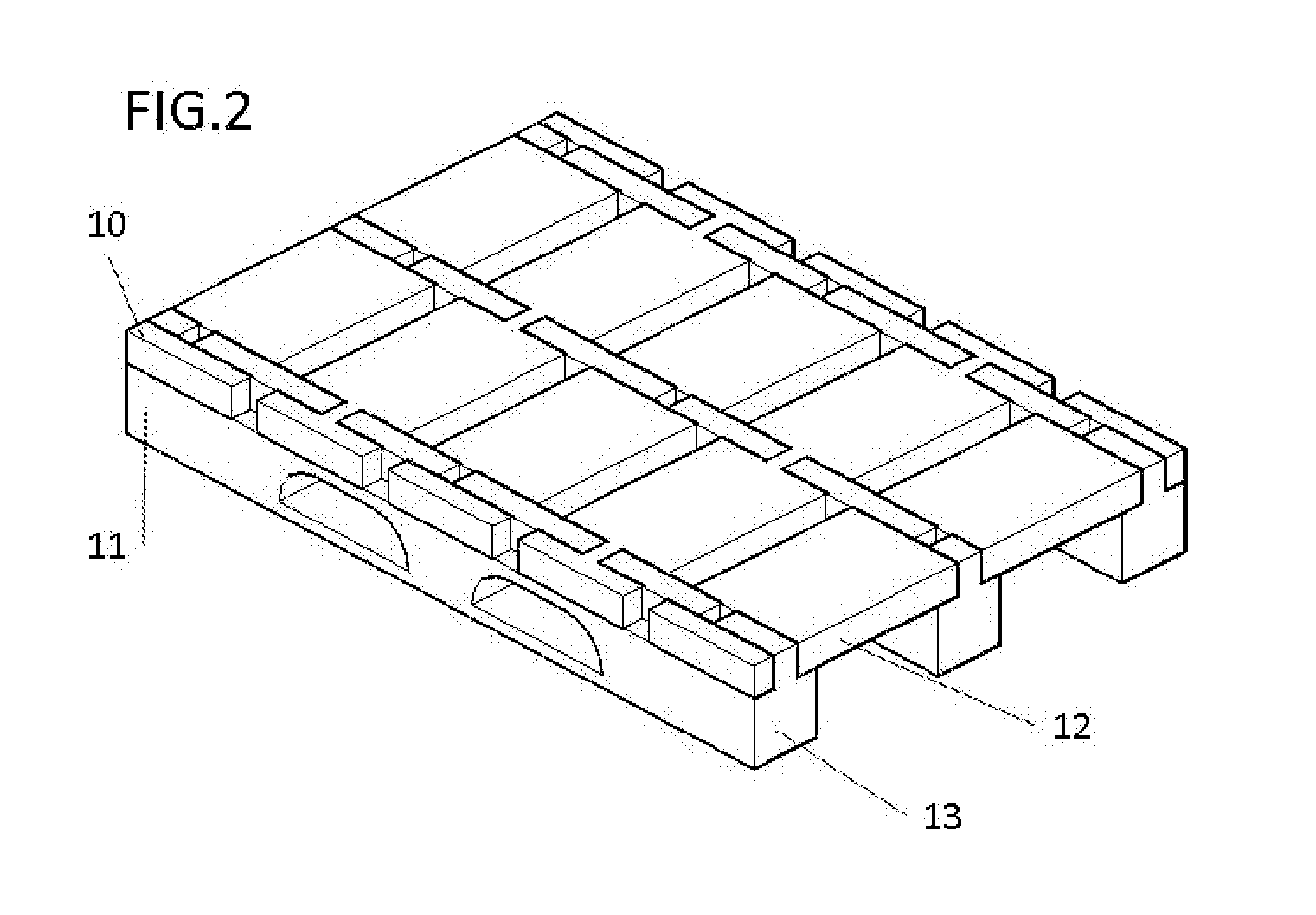
[0048]As indicated above, the invention relates to a dismantlable self-assembly structure applicable in several sectors, although the tests performed show that it is ideal for use in the transportation sector, specifically to make pallets; this example is used to explain an embodiment of the invention represented in FIGS. 1 and 2, which is not the only one possible.

[0049]The pallet according to the proposed embodiment comprises three longitudinal members (1) and five cross members (2).

[0050]Each one of the longitudinal members comprises an elongated parallelepiped body with the lower part thereof thicker than the upper part thereof, a recess (7) determining the difference in thickness between the lower and upper parts.

[0051]At the top part the longitudinal member has a number of slots (4) that prolong downward to form an “L”.

[0052]Said slots are suitable for inserting therein the cross members (2) at the narrowed area thereof.

[0053]To do so it is necessary to arrange the longitudina...


PUM


Abstract

The invention relates to a self-assembly formed by a series of longitudinal members and cross members, all of the longitudinal members being identical to one other and all of the cross members being identical to one other, such that only two types of parts are required to construct the structure. Owing to the shape of the parts, they can be assembled to one another to create a solid structure without requiring any other connecting materials or elements. The longitudinal members comprise a series of slots into which narrowed segments of the cross members are inserted. Once the cross members have been inserted into the slots they are trapped therein by moving the longitudinal members and, in order to prevent this movement occurring in the opposite direction, other cross members are inserted into slots provided in the longitudinal members for this purpose.

Description

[0001]The present invention, as indicated by its name, relates to a self-assembly structure consisting of a series of longitudinal and cross members which, due to their shape, can be assembled to each other generating a solid structure without requiring any additional connecting element or material.[0002]The construction and assembly of the structure requires only two types of parts which, arranged differently depending on the intended purpose thereof, manage to compose and provide solidity to the structure.[0003]The field of the art to which it belongs is that of transportable structures.BACKGROUND OF THE INVENTION[0004]Although the type of structure disclosed can have many uses and applications, it is optimal for use as a transportation pallet; in fact, this is a sector in which the closest prior art documents, discussed below, have been found.[0005]Pallets have been used for a long time to transport loads. However, said pallets must make several trips without a load.[0006]In long...

Claims


Application Information

Patent Timeline
IPC IPC(8): B65D19/00
CPCB65D19/0073B65D2519/00985B65D2519/00567B65D19/0095B65D2519/00273B65D2519/00293B65D2519/00323B65D2519/00333B65D19/20
Inventor MARCONEL CARPIO, JOSE LUISGARCIA GUILLEN, TOMAS ANDRES
Owner AVANTPACK
Learn More