Laser exposure apparatus for exposing a screen held in a frame

a technology of exposure apparatus and frame, which is applied in the direction of laser details, printing, rotary presses, etc., can solve the problems of not being able to adapt to automatic screen printing machines, and achieve the effects of accurate positioning, low cost and reduced cos

Inactive Publication Date: 2006-09-07
LINDTHALER JOSEF
View PDF7 Cites 0 Cited by
  • Summary
  • Abstract
  • Description
  • Claims
  • Application Information

AI Technical Summary

Benefits of technology

[0012] Another advantage of the laser exposure apparatus is that the screen is brought into the final position, together with the frame, by placing it onto the screen holding device. The frame is thereby accurately placed and retained by the positioning pins while the screen is stretched by the self-weight of the frame. As a result, the screen can be mechanically placed onto the screen holding device, thus reducing the cost.
[0013] It has thereby been found advantageous to configure the positioning openings to correspond to, and register with the positioning pins with zero clearance with respect thereto, in order to achieve exact positioning of the screen.
[0014] In another preferred embodiment, it has been found advantageous to configure one positioning opening as a long hole and to keep the other positioning opening circular. This not only permits to ensure, via the circular positioning opening, the exact positioning of the screen and to reliably prevent, via the second positioning pin, the screen from slipping or rotating out of place but also to prevent, via the long hole, the frame from jamming when the screen is being placed into, or removed from, the screen holding device.
[0015] Another advantage is that such a screen stretching device configured to be a screen support can be manufactured at very low cost since it has a simple construction and no movable parts.
[0016] In a preferred embodiment, it has been found advantageous to configure the screen support as a perimeter ledge projecting upward, a planar supporting surface being formed on said ledge. The advantage thereof is that such a ledge provides a large supporting surface for the screen so that the surface pressure will more specifically remain low, with no damage to the screen. In an alternative embodiment, the screen support is formed from at least four stamps extending upward, each stamp comprising a planar supporting surface with the supporting surface and the stamp being aligned. Such a screen support formed from stamps can be manufactured at low cost and also stretches the screen in the manner described herein above.
[0017] It has thereby been found advantageous to dispose the screen support on the border of the screen although not in the region of the frame so that the screen will be stretched and the area to be exposed still relatively large.

Problems solved by technology

Such positioning is not suitable for an automated screen printing machine since the screen may slip out of place as the table is moved beneath the laser exposure device.

Method used


Image

  • Laser exposure apparatus for exposing a screen held in a frame
  • Laser exposure apparatus for exposing a screen held in a frame
  • Laser exposure apparatus for exposing a screen held in a frame

Examples


Embodiment Construction

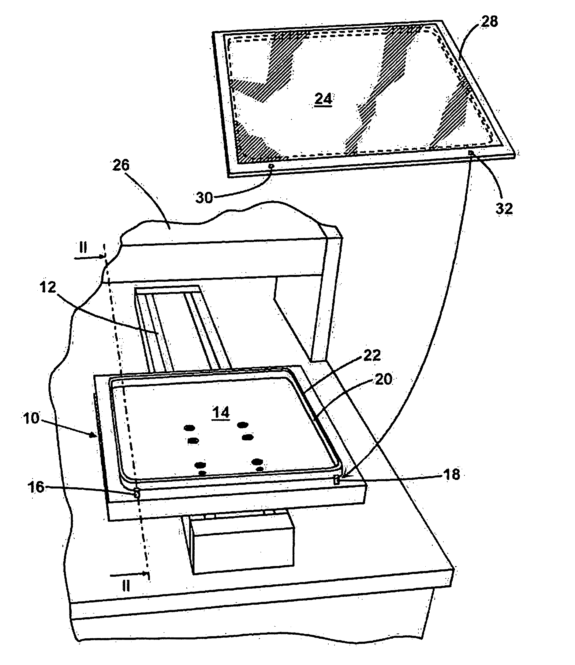
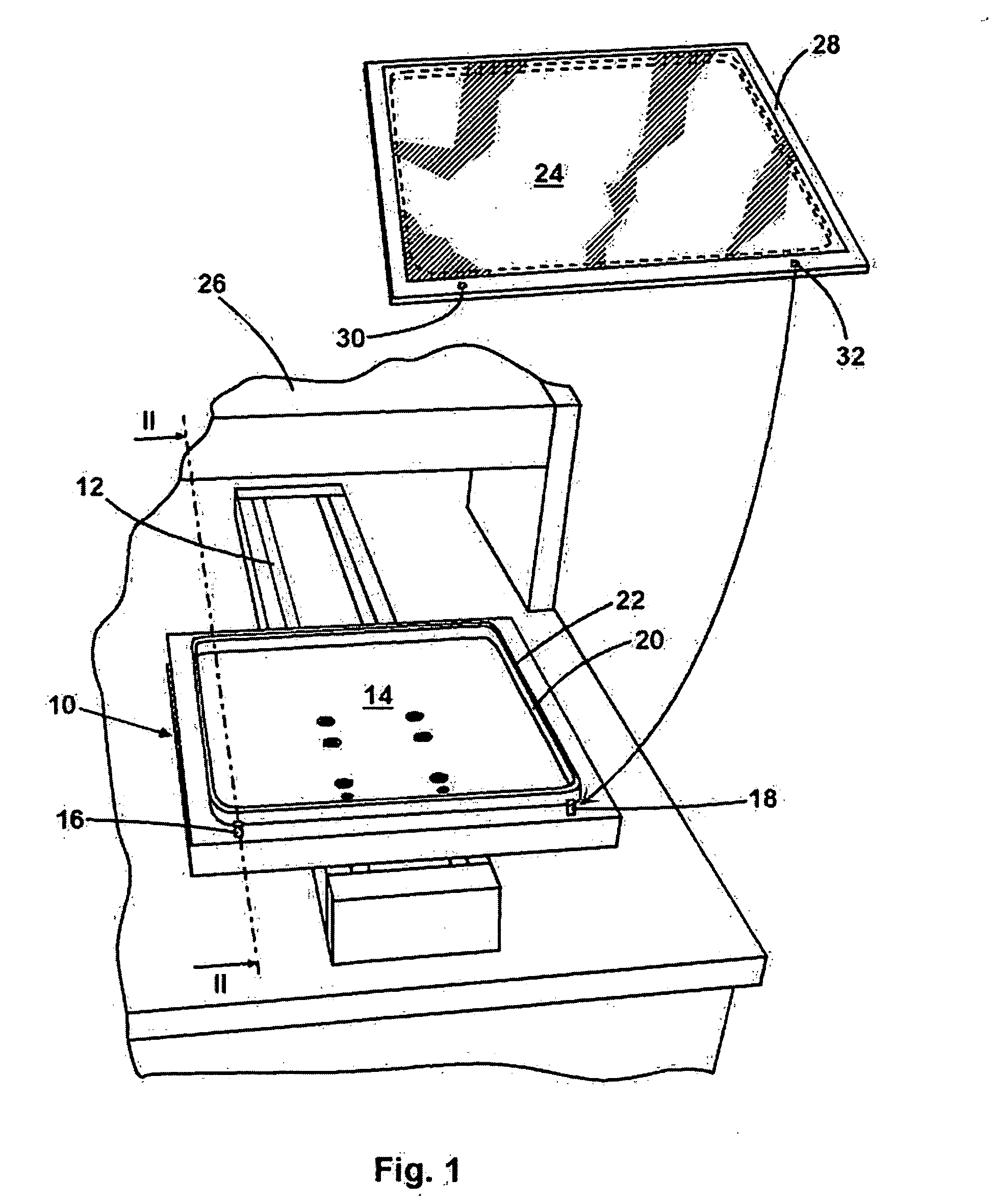
[0026]FIG. 1 is a perspective view showing a part of a laser exposure apparatus according to the present invention. This laser exposure apparatus includes a linearly displaceable screen holding device 10 that is held for linear displacement in a corresponding guide track 12. The screen holding device 10 includes a substantially horizontally oriented table 14 on the border of which there are mounted two vertically protruding positioning pins 16, 18. Further, a perimeter and upwardly protruding ledge 20 on the upper side of which there is formed a screen support 22 is provided on said table 14. The upper side of the ledge 20 is thereby configured to be a planar supporting surface on which a screen 24 may be placed.

[0027] A box 26 of the laser exposure apparatus, which has merely been outlined herein, accommodates the laser itself and the screen holding device 10 traveling along the guide track 12 may be moved beneath the laser in such a manner that the screen 24 resting on the screen...


PUM


Abstract

The subject matter of the invention is a laser exposure apparatus for exposing a screen (24) held in a frame (28), more specifically for Computer-to-Screen exposure. A low-cost method and a low-cost laser exposure apparatus of the type mentioned herein above by means of which the screen is readily held in an accurately defined position during exposing are achieved by having the screen holding device (10) including a screen support (22) with a defined supporting surface, with the screen support (22) being disposed in such a manner that the screen (24) is adapted to be placed onto said screen support (22) whilst the frame (28) is freely suspended beside said screen support (22), being held by said screen (24), and that at least one positioning pin (16, 18) mounted to said screen holding device (10) engaging into a positioning opening (30, 32) provided on said frame (28) if said screen (24) rests on said screen support (22).

Description

FIELD OF INVENTION [0001] The present invention relates to a laser exposure apparatus in accordance with the preamble of claim 1. In screen printing, the light-sensitive screens are exposed by laser exposing with a certain image and then coated with an emulsion that only adheres to the areas intended for this purpose. On the other areas of the screen to which the emulsion did not adhere, the desired color may then pass through the screen and reach the element that is to be printed. During laser exposure, a laser is focused on the screen through a corresponding optics in order to reproduce the image on the screen. In order for the image on the screen to be sharp, it is important that the screen be effectively placed in the focus of the laser. The screen only needs be out of focus by one tenth of a millimetre to produce a blurred image. DESCRIPTION OF THE PRIOR ART [0002] Using inkjet printers or wax coating methods, EP 0 811 484 Al in particular teaches to place the screen onto a sup...

Claims


Application Information

Patent Timeline
Patent Type & Authority Applications(United States)
IPC IPC(8): H01S3/14
CPCB41C1/145B41F15/36
Inventor LINDTHALER, JOSEF
Owner LINDTHALER JOSEF
Why Eureka
Try Eureka