
Milling tool for small slot machining

A milling tool and slot machining technology, applied in milling cutting inserts, milling cutters, manufacturing tools, etc., can solve problems such as easy breakage, high production cost, and inability to meet market demands.

Inactive Publication Date: 2019-01-04
AVIC STANDARD PARTS MFG
View PDF9 Cites 0 Cited by
  • Summary
  • Abstract
  • Description
  • Claims
  • Application Information

AI Technical Summary

Problems solved by technology

The disadvantage is that because the grinding head of the sharpening machine does not match the shape of the edge of the blade, more blade material must be ground during sharpening to remove the broken part, and there is a groove behind the blade to support the part of the blade Less, the blade is easy to break, resulting in difficult sharpening, easy to break, and high production costs
Unable to meet the needs of the market

Method used


Image

  • Milling tool for small slot machining
  • Milling tool for small slot machining
  • Milling tool for small slot machining

Examples


Embodiment Construction

[0018] The specific implementation, features and functions of the milling tool for machining small grooves according to the present invention will be described in detail below in conjunction with the accompanying drawings and preferred embodiments.

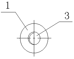
[0019] see Figure 1 to Figure 3 , a kind of milling tool for small groove processing of the present invention, comprises blade body 1, blade A2, blade B3, wherein: blade A2, blade B3 integrated with blade body 1 are respectively provided at the left and right ends of blade body 1.

[0020] The middle part of the blade body 1 is cylindrical, and the two ends are conical.

[0021] The cutting edge of the blade A2 is a half-opened meniscus.

[0022] The blade A2 can be fed radially or axially.

[0023] The cutting edge of the blade B3 is a half-opened meniscus.

[0024] The blade B3 can be fed radially or axially.

[0025] When in use, the middle part of the blade 1 is clamped on the machine tool as the clamping part. The cutti...


PUM


Abstract

The invention discloses a milling tool for small slot machining. The milling tool comprises a tool body (1), a cutting edge A (2) and a cutting edge B (3), and is characterized in that the cutting edge A (2) and the cutting edge B (3) which are integrated with the tool body (1) are arranged at the left and right ends of the tool body (1) respectively. The milling tool is convenient to sharpen, hard to break and low in cost.

Description

technical field [0001] The invention belongs to the technical field of milling, and in particular relates to a milling tool for machining small grooves. Background technique [0002] In the process of mechanical processing, the end mills used for milling small grooves of various parts are frequently used. During milling, the end mills are in contact with the workpiece during milling, and the end mills are easily damaged and scrapped, even if the unbroken tool , After the blade is worn, it needs special equipment for heavy sharpening before it can be used. [0003] Prior art Chinese patent; application number: 2017218363920, publication number 207629275U, specifically discloses an end mill, comprising a cylindrical handle and a cutter head positioned at the end of the handle, the side wall of the cutter head is helically arranged There are four grooves, and the four grooves form four blades at the top of the cutter head, and the blades include a knife surface, a top surface ...

Claims


Application Information

Patent Timeline
IPC IPC(8): B23C5/02
CPCB23C5/02B23C2200/04
Inventor 刘勇田亮
Owner AVIC STANDARD PARTS MFG
Learn More